What TDLAS is
Laser-based gas analysis, explained
Tunable Diode Laser Absorption Spectroscopy (TDLAS) is an optical technique for measuring gas concentration. The wavelength of the light from a diode laser is tuned to a wavelength where the target gas absorbs the light. As the laser beam is passed through the interrogation volume, if the target gas is present, part of the light will be absorbed by the gas molecules, and the concentration can be calculated based on the amount of light that reaches the detector. Because every gas species absorbs light at its own characteristic wavelengths, the measurement is highly specific without interference from other gas species in the background gas mixture.
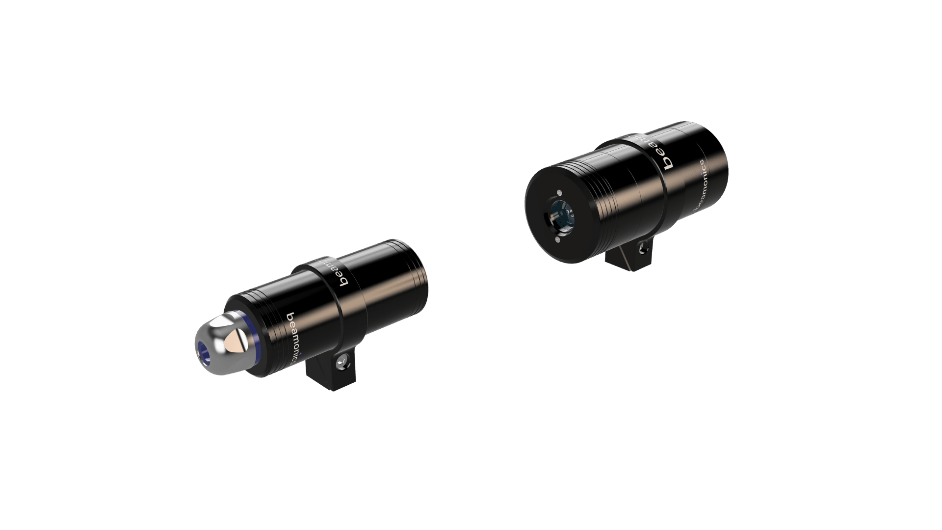
Beamonics designs and manufactures TDLAS instruments in Lund, Sweden, in three optical configurations: cross-stack/duct, extractive, and standoff. The Beamonics analysis technology is self-referencing through the use of narrow-band laser diodes which can address individual molecular absorption lines, thus providing instruments that have no drifts over time and are well suited for long-term continuous gas analysis with minimal maintenance needs.
How it works
From absorption line to concentration
A narrowband diode laser is scanned across a single or multiple gas absorption lines of the target species. The transmitted intensity is known, so any light removed on the way to the detector is attributable to absorption by the gas along the optical path. By applying the Beer-Lambert law, the measured absorption is converted to concentration.
Careful line selection is an inherent part of the Beamonics design process, and the analyzers as such offer minimal to no cross-interference. The measurements are very fast, non-contact, non-destructive, and independent of gas flow rates, so nothing is perturbed in the processes, and nothing is consumed.
Scroll sideways to pan the diagram
Line selection and scanning
For each target gas, the light source is matched to the absorption spectrum, often targeting the line with the strongest absorption and lowest cross-interference with other species. Once the target line is identified, a laser is used to scan across the absorption line.
Intensity at the detector
Since the transmitted intensity without gas absorption is known, the absorption by the target gas will create a dip in the intensity reaching the receiver at the specific wavelength where the target gas absorbs, if it is present.
Concentration, temperature, pressure
The dip is turned into an absorption spectrum, from which gas concentration, temperature, and pressure are calculated. The technique is inherently self-referencing and does not require regular recalibration.
Measured performance
Precision by product and gas
Precision depends on the gas, the optical path length, and the integration time, so the figures below are given with the test conditions they were measured under. BeamStack® and BeamCell® report concentration in ppm or vol%. BeamSight® reports path-integrated concentration in ppm·m, because the optical path in a standoff measurement is variable and not known to the instrument.
| Gas | Precision (ppm) |
|---|---|
| O2 | 6 |
| HF | 0.01 |
| CO | 0.2 |
| CO2 | 0.5 |
| CH4 | 0.2 |
| H2S | 0.3 |
| NH3 | 0.2 |
| H2O | 0.2 |
| Gas | Precision (ppm) |
|---|---|
| O2 | 30 |
| HF | 0.05 |
| CO | 1 |
| CO2 | 2.5 |
| CH4 | 1 |
| H2S | 1.5 |
| NH3 | 1 |
| H2O | 1 |
| Gas | Precision (ppm·m) |
|---|---|
| HF | 0.05 |
| CO | 15 |
| CO2 | 40 |
| CH4 | 15 |
| H2S | 25 |
| NH3 | 15 |
Full specifications, gas tables, and test conditions for all three analyzers are in the product datasheets.
Request the datasheetsOptical configurations
Three ways to analyze gas with a laser
The measurement principle is the same in all three Beamonics products. The differences are primarily related to the optical path relative to the process gas, and the most optimal configuration is often dependent on the specific application. The three configurations are thus complementary rather than alternatives.
BeamStack®
ppm·full duct analysis·IP67
The transmitter and receiver are installed on opposite sides of a duct, stack, pipe, or open space, and the beam passes directly through the process gas. Nothing is extracted and nothing is conditioned, so there is no sample line to maintain and no transport delay between the process changing and the reading changing.
Full-diameter gas analysis across the duct averages over the whole cross-section rather than sampling one point, which matters where the gas is stratified. In-situ measurements are common in combustion systems, exhaust ducts, biogas lines, and high-temperature processes.
Scroll sideways to pan the diagram
Scroll sideways to pan the diagram
BeamCell®
ppm·0.185 m cell·IP67
Gas is drawn into an internal optical flow-chamber (cell) where pressure and temperature are held stable, and absorption is measured under defined conditions. Controlling the conditions is what makes the configuration suited for complex mixtures, varying process pressures or enclosed systems, and installations where one analyzer serves several sample points.
The flow chamber is resistant to corrosion and withstands aggressive chemicals including sulfuric acid, hydrogen chloride and hydrogen fluoride, which is why extractive analysis often can be the right answer for aggressive species rather than a fallback when optical access is awkward. Connections are G1/8 push-in for 6 mm or 8 mm tubing.
BeamSight®
ppm·m·30 m unaided, 100 m with reflector·IP44
The instrument points at a target and reads the gas between itself and whatever surface returns the beam, with no installation on the process at all. Detection runs to 30 m against an unaided back-reflection and over 100 m where a reflector is fitted, with a minimum working distance of 0.2 m.
Laser and detector are in the same housing, so there is no receiver at the far end to mount, align, or cable back. Commissioning is a matter of pointing the instrument, which is what makes it practical for survey work across a tank farm, leak analysis of a site, or a fence line where installing opposed optics at every point of interest would not be practical.
Because the optical path length is set by the geometry of each measurement and is not known to the instrument, BeamSight reports path-integrated concentration in ppm·m rather than ppm. The BeamSight unit is the correct one for leak searching and survey work, where the question is whether gas is present along a line of sight. Fixed, portable battery-powered, and drone- or rover-mounted variants share the same platform.
Scroll sideways to pan the diagram
Which configuration fits depends on optical access, the species, and the application. Talk to our engineers to get recommendations of the gas analyzer best suited for your application.
Talk to an engineerGas coverage
Gases measured with TDLAS
Selectivity comes from the optical gas absorption line rather than from a chemical reaction, so an individual species can be measured against a complex background. Which gases a given instrument can target depends on the laser, detector and configuration choices.
- Oxygen O2
- Carbon dioxide CO2
- Carbon monoxide CO
- Methane CH4
- Ammonia NH3
- Water vapor H2O
- Hydrogen fluoride HF
- Hydrogen chloride HCl
- Hydrogen sulfide H2S
- Nitrous oxide N2O
Addressable gases differ by product. The current BeamStack datasheet lists O2, CO2, CO, N2O, NH3, HF, H2S, H2O, HCl and CH4. The BeamCell datasheet lists the same set without N2O, and the BeamSight datasheet lists CH4, CO2, CO, HF, H2S and NH3. A published gas table records the lines already characterised for that instrument rather than the limit of what the platform can target, so ask about a species that is not listed.
Scroll sideways to pan the diagram
How TDLAS compares
TDLAS against the methods it usually is compared to
Most sites already rely on gas measurements. The section below summarizes where TDLAS differs from the specific technique in question, and where the other method still holds an advantage. Each row links to a longer description.
| Method | Main difference in practice | Where it still wins | |
|---|---|---|---|
| Electrochemical cells | Consumable sensing elements with finite life-times and diffusion-limited responses. TDLAS has no consumables and no reaction delays. | Low unit cost and small portable form factors for personal safety monitoring. | Read |
| FTIR | Complex broadband spectral measurement across many species at once, high maintenance requirements and requires careful sample handling. TDLAS targets one line and runs continuously in the process without maintenance. | Simultaneous quantification of many components from one spectrum. | Read |
| Gas chromatography | Batch separation with a cycle time between results and large consumable requirements. TDLAS produces continuous readings suitable for closed-loop control without any consumables. | Full compositional breakdown of an unknown mixture. | Read |
| CRDS | Laser-based extractive gas analysis using cavity ring-down times (relaxation time after excitation) often with very long path lengths. TDLAS deploys directly in-process without the need of a high-finesse cavity. | Trace detection at the lowest concentrations in controlled sampling conditions. | Read |
| FID for hydrocarbons | Requires fuel gas and a flame, with demanding consumable supply logistics. TDLAS has no consumables and only requires power and optical access. | Total hydrocarbon measurement across a broad range of compounds. | Read |
Wider context: where TDLAS fits among trace gas analysis methods, total cost of ownership, and when TDLAS justifies its cost and when it does not.
Before you specify
Choosing the right configuration
TDLAS may not be the right measurement technology for everything, and the constraints are worth considering before an installation is designed or commissioned.
Optical access is required
The light needs to pass through the gas via, for example, opposing flanges on a duct, a sample cell, or a clear line of sight to a return surface. Where none of those are available, measurements cannot be made.
Path length sets the detection floor
Absorption scales with the optical path length of the beam through the gas, so a longer path detects lower concentrations. A short cell and a wide stack give different lower detection limits for the same gas, which is why the precision figures above are meaningless without their optical path lengths.
Heavy particulate attenuates the beam
Dust and droplets reduce transmission. Beamonics instruments handle low transmission thanks to the proprietary digital platform, which allows uninterrupted operation without regular cleaning and recalibration. However, attenuation is a physical constraint and too high attenuation will eventually create photon-starved and noisy analysis results.
Standoff reads ppm·m, not ppm
A remote measurement integrates over an unknown path, so it provides the amount of gas present along a line of sight rather than what the concentration is at a specific point in space. For a control loop that needs the concentration in ppm or vol%, a cross-stack or extractive configuration is the correct choice.
Water blocks the beam in extractive lines
Condensates and liquids in a sample line prevent light from reaching the detector. This is beam blockage rather than cross-interference, and should be handled at the sample conditioning stages.
Targeted species of an instrument
A TDLAS analyzer is configured for the gases it is built to measure. Where an unknown mixture has to be broken down component by component, a multi-component analysis method such as GC or FTIR is the better fit.
Solid and long lifetime
Laser and detector lifetimes are in the ten-year range when operated within specification, with robust replaceable components built for long lifetimes.
Related reading: choosing between in-situ, extractive, and remote TDLAS configurations.
Common questions
TDLAS questions engineers ask
What does TDLAS stand for
TDLAS stands for Tunable Diode Laser Absorption Spectroscopy. The wavelength of the light from a diode laser is tuned to a wavelength where the target gas absorbs, and the gas concentration is calculated from the amount of light that reaches the detector, using the Beer-Lambert law.
Does a TDLAS analyzer need calibration
The Beamonics analysis technology is self-referencing through the use of narrow-band laser diodes which can address individual molecular absorption lines. The instruments therefore have no drifts over time and do not require regular recalibration, which is what makes them suited to long-term continuous gas analysis with minimal maintenance needs.
Which gases can TDLAS measure
Beamonics instruments measure O2, CO2, CO, CH4, NH3, H2O, H2S, HF, HCl and N2O, with coverage varying by product. Any gas with accessible absorption lines in the near or mid infrared can in principle be targeted; homonuclear diatomic species, other than O2, are the general exception. A published gas table records the lines already characterised for that instrument rather than the limit of what the platform can target, so ask about a species that is not listed.
What is the difference between ppm and ppm·m
A ppm reading is a concentration measured over a known optical path length. A ppm·m reading is path-integrated: the concentration multiplied by the length of gas the beam crossed. Standoff instruments report ppm·m because the optical path is set by the geometry of each measurement and is not known to the instrument. BeamStack and BeamCell report ppm or vol%; BeamSight reports ppm·m.
What is the difference between in-situ, extractive and standoff measurement
In-situ measurement passes the laser directly through the process gas inside a duct, stack or pipe, with no sampling and no transport delay. Extractive measurement draws gas into an optical flow-chamber where pressure and temperature are held stable, which suits complex mixtures, varying process pressures and multi-point installations. Standoff measurement points the instrument at a target and reads the gas along the line of sight, with no installation on the process at all. Beamonics builds all three: BeamStack is in-situ, BeamCell is extractive, and BeamSight is standoff.
Can TDLAS measure through dust
Dust and droplets reduce transmission. Beamonics instruments handle low transmission thanks to the proprietary digital platform, which allows uninterrupted operation without regular cleaning and recalibration. Attenuation is a physical constraint, so too high attenuation will eventually create photon-starved and noisy analysis results.
How is the optical path length chosen
Absorption scales with the optical path length of the beam through the gas, so a longer path detects lower concentrations. A short cell and a wide stack give different lower detection limits for the same gas, which is why a precision figure is meaningless without the path length it was measured over. In practice the path is set by the installation, and the configuration is chosen to suit it.