In Brief
TDLAS and CRDS are both laser-based techniques for measuring gas concentration through molecular absorption. CRDS achieves lower absolute detection limits, into the parts-per-trillion range, by trapping laser light inside an optical cavity to create effective path lengths of several kilometers. TDLAS operates at ppb-level sensitivity using direct absorption and signal modulation, in instruments compact enough to mount on process equipment or carry by hand. For industrial gas monitoring, where detection requirements are typically in the ppb to ppm range, TDLAS provides the needed sensitivity with less complexity and lower cost. CRDS fills a distinct role in trace-atmospheric research, isotope analysis, and calibration gas verification, where sub-ppb measurement is required and the environment permits a more demanding instrument.
The same physics, different optical strategies
Both TDLAS and CRDS measure gas concentration by exploiting molecular absorption: when a laser beam passes through a gas, molecules of the target species absorb light at wavelengths specific to their quantum structure. The fraction of light absorbed is proportional to the gas concentration and the distance the light travels through the gas, a relationship described by the Beer-Lambert law.
The difficulty arises when gas concentrations are very low. A trace-level gas over a short optical path produces an absorption signal that is small relative to noise. TDLAS and CRDS solve this problem differently.
In a TDLAS instrument, a tunable diode laser scans rapidly across a narrow wavelength range centered on a single absorption line of the target gas. Modulation and digital signal processing techniques extract the absorption feature from background noise. The result is a measurement that is selective to one molecular species, immune to interference from other gases, and referenced to molecular physics rather than to an external calibration standard. The instrument achieves this with no optical cavity, no moving parts, and no critical alignment requirements. Sensitivity scales with path length: longer optical paths yield lower detection limits. In a cross-stack or open-path configuration, path lengths of 1 m or more are common. In a compact extractive cell, 0.2 m is typical.
CRDS takes a fundamentally different approach to the path-length problem. Instead of extending the physical path, it multiplies it optically. A laser pulse enters a cavity formed by two highly reflective mirrors, typically above 99.99% reflectivity, and bounces back and forth thousands of times before the light decays. The instrument measures the time constant of that exponential decay, called the ring-down time. When an absorbing gas fills the cavity, it accelerates the decay. The difference between the empty-cavity and gas-filled ring-down times yields the gas concentration.
Because the measurement is a time interval rather than a comparison of light intensities, CRDS is inherently insensitive to laser power fluctuations. The effective optical path length, determined by mirror reflectivity and cavity geometry, can reach several kilometers from a physical cell only 20 to 50 cm long. That enormous effective path is what enables CRDS to detect gases at concentrations two to three orders of magnitude lower than direct absorption TDLAS.
What CRDS demands in practice
The sensitivity of CRDS comes with engineering constraints that follow directly from the cavity design. Mirror surfaces must maintain their extreme reflectivity over time. Any contamination, whether from particulate, condensable vapors, or chemical deposits, shortens the ring-down time and introduces measurement error that is difficult to distinguish from a real change in gas concentration. Sample conditioning systems are therefore essential: the gas entering the cavity must be clean, dry, and free of species that could coat the mirror surfaces.
Cavity alignment is sensitive to mechanical vibration and thermal expansion. A shift of microradians in mirror angle can degrade or eliminate the cavity mode structure. Commercial CRDS instruments are typically shelter-mounted and installed on vibration-isolated platforms, not bolted to ductwork or mounted on process equipment.
These are not deficiencies in the technology. They are consequences of using an optical cavity with 99.99%+ reflectivity mirrors as the measurement element. In a university atmospheric research station or a calibration gas laboratory, these requirements are straightforward to meet. In a cement plant, a refinery, or a biogas upgrading facility, they represent a significant infrastructure and maintenance burden.
Detection limits and where they matter
CRDS can achieve parts-per-trillion sensitivity for gases including CO₂, CH₄, N₂O, and water vapor isotopologues. This makes it the standard instrument for atmospheric trace gas monitoring at baseline stations, for stable isotope ratio measurement in hydrology and paleoclimate research, and for verifying the purity of ultra-high-purity calibration gases.
Industrial gas monitoring operates in a different concentration regime. HF monitoring in aluminum smelting or semiconductor fabrication targets sub-ppm to tens of ppm. CO measurement for combustion optimization ranges from single-digit ppm upward. NH₃ monitoring in selective catalytic reduction systems or fertilizer production operates in the low-ppm range. H₂S detection in biogas upgrading, natural gas processing, or refinery operations is relevant from fractions of a ppm to hundreds of ppm.
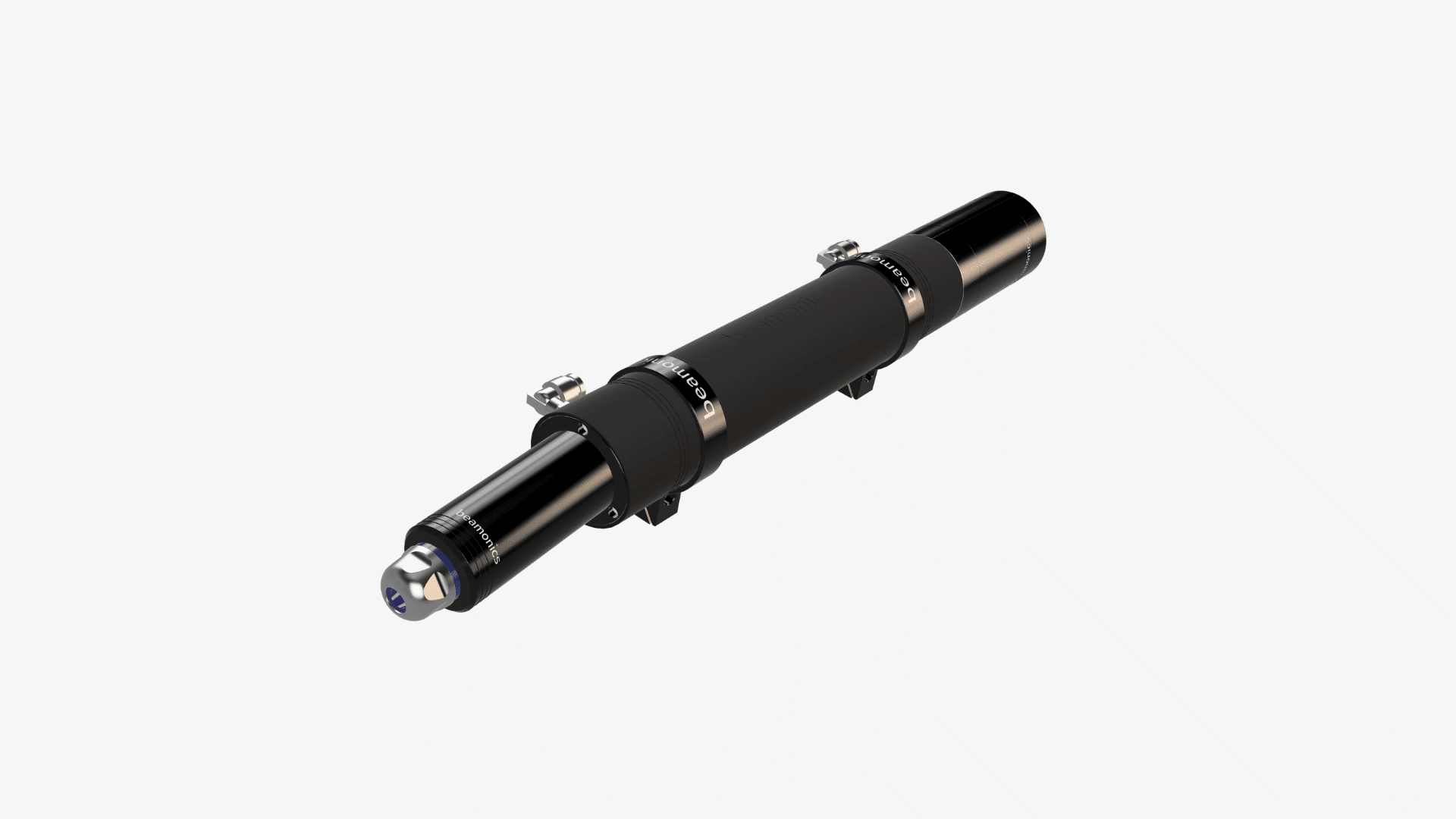
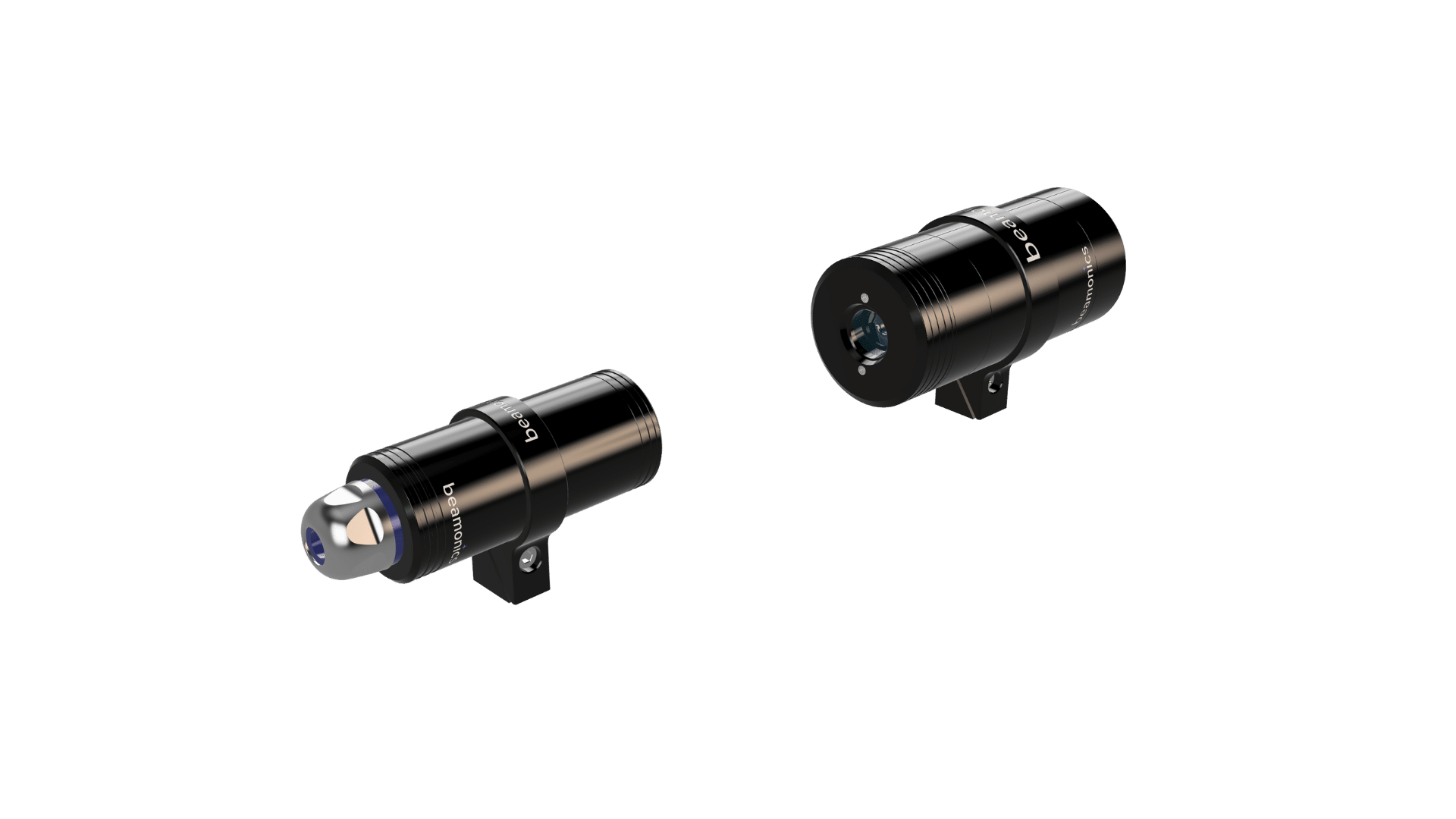
TDLAS covers all of these with margin. The Beamonics BeamStack (BM-H-3), a cross-stack TDLAS analyzer with a 1 m path length, achieves analysis precision of 0.01 ppm for HF, 0.2 ppm for CO, 0.5 ppm for CO₂, 0.2 ppm for CH₄, 0.3 ppm for H₂S, and 0.2 ppm for NH₃ under standard test conditions (1 s averaging, 1 atm, 300 K). The BeamCell (BM-H-3), an extractive flow-through analyzer with a 0.2 m path length, reaches 0.05 ppm for HF, 1 ppm for CO, 2.5 ppm for CO₂, 1 ppm for CH₄, 1.5 ppm for H₂S, and 1 ppm for NH₃ under equivalent conditions. These figures are well below the alarm and control thresholds used in practice.
The question is not which technique has the lower detection limit in absolute terms. The question is whether the application requires sensitivity below what TDLAS provides. If it does, CRDS is justified. If it does not, the additional optical complexity, cost, and environmental sensitivity of a cavity-based instrument are unnecessary.
Deployment and installation
TDLAS analyzers for industrial use are designed to operate where the measurement needs to happen, not in a separate analytical shelter. The BeamStack mounts directly as a cross-stack pair or open-path transmitter-receiver, measuring gas in situ without extracting a sample. IP67-rated enclosures withstand the temperature range of −10 °C to 55 °C and the moisture, dust, and vibration typical of heavy industrial environments. The BeamCell integrates into sampling systems via G1/8 push-in connectors for 6 mm or 8 mm gas tubing, with an acid-resistant flow chamber that handles corrosive species including H₂S and HF. Startup time for both instruments is approximately 5 seconds.
The BeamSight (BM-V-2) extends TDLAS to remote stand-off measurement, detecting gases at distances up to 30 m (100 m with a reflector) without any physical contact with the gas. The battery-powered portable configuration weighs 1.0 kg and operates for approximately 5 hours, enabling drone-mounted surveys, handheld leak detection, and rapid area screening. No CRDS instrument offers a comparable portable or remote configuration.
CRDS instruments, by contrast, are precision laboratory assemblies. Commercial process-grade CRDS analyzers exist, but they require shelter installation, clean dry sample delivery, vibration isolation, and stable temperature control. Mirror cleaning or replacement requires trained personnel and careful realignment. Sample conditioning adds tubing, filters, dryers, and pumps upstream of the analyzer, increasing both the system footprint and the number of potential failure points.
Specification comparison
| Parameter | TDLAS (industrial) | CRDS |
|---|---|---|
| Typical sensitivity | ppb range | ppt range achievable for select gases |
| Response time | 1 to 2 s typical; analysis rates up to 10 kHz | Seconds to tens of seconds |
| Effective path length | Physical path: 0.2 m (extractive) to open-path | Effective km-scale via optical cavity |
| Selectivity | Single absorption line; no cross-talk | Single absorption line; no cross-talk |
| Deployment environment | Industrial; IP67 available; portable battery-powered | Controlled; vibration-sensitive; shelter-mounted |
| Optics maintenance | Cleaning at 6 to 12 month intervals | Mirror contamination is primary failure mode |
| Calibration | Factory-calibrated; self-referencing; no routine field span | Stable ring-down time reference; no routine field span |
| Capital and infrastructure cost | Moderate | High, plus sample conditioning and shelter |
| Portability | Fixed, or battery-powered portable (0.7 to 1.0 kg) | Fixed installation only |
| Primary fit | Process control, safety, emissions compliance | Atmospheric research, isotope analysis, calibration gas purity |
Considerations
- CRDS mirror degradation is cumulative and not always immediately obvious. A gradually shortening ring-down time can mimic a slow rise in background concentration, creating a subtle systematic error that is difficult to detect without periodic cavity verification.
- TDLAS detection limits scale with optical path length. For applications near the edge of required sensitivity, specifying a longer path (for example, cross-stack rather than extractive) may be sufficient to avoid the step up to CRDS.
- Both techniques are calibration-stable through different mechanisms: TDLAS through self-referencing against the molecular absorption line shape, CRDS through the independence of ring-down time from laser power. Neither requires routine field span calibration.
- CRDS sample conditioning systems (dryers, filters, pressure regulators) introduce their own failure modes and can affect measurement accuracy if not maintained. The total system reliability includes these components, not just the analyzer itself.
- For multi-gas monitoring at a single location, TDLAS can be configured with different laser modules targeting different absorption lines. CRDS instruments are typically optimized for one gas or a narrow group of gases per cavity, and multi-species measurement may require multiple instruments.
Closing remark
CRDS and TDLAS occupy different positions on the sensitivity-versus-practicality spectrum, and most applications clearly favor one or the other. Where the measurement target is in the ppb to ppm range and the environment is industrial, TDLAS provides the required sensitivity in an instrument designed for that setting. Where sub-ppb measurement is the requirement and the deployment allows a controlled analytical environment, CRDS is the established approach. The overlap between these two domains is narrow. Identifying the actual detection requirement and the installation conditions resolves the choice in the large majority of cases.
Related links
- Product page: BeamStack (BM-H-3), cross-stack and open-path TDLAS analyzer
- Product page: BeamCell (BM-H-3), extractive flow-through TDLAS analyzer
- Product page: BeamSight (BM-V-2), remote stand-off TDLAS analyzer
- Tech article: TDLAS vs. traditional fixed-point gas detectors
- Tech article: How TDLAS works, measurement principle explained