In Brief
Combustion optimization in power plants requires continuous measurement of exhaust gas composition, primarily CO and O₂ to control the air-fuel ratio, and CO₂ as an indicator of combustion completeness, fuel carbon conversion, and emissions intensity. These three gases together define the combustion operating envelope: too much air wastes energy, too little produces CO and unburned fuel, and the CO₂ concentration tracks the carbon balance through the process. Beamonics TDLAS analyzers provide the response speed, selectivity, and long-term stability needed for real-time combustion control in the high-temperature, high-dust, high-moisture flue gas environment of coal, gas, biomass, and waste-fired power plants.
Background
Power generation by combustion of fossil fuels, biomass, or waste-derived fuels converts chemical energy in the fuel to heat, and the efficiency of that conversion depends on how completely the fuel carbon oxidizes to CO₂ and how little of the heat is lost to heating excess air. These two objectives are in tension. Increasing the air supply improves carbon burnout and reduces CO, but it also increases the volume of nitrogen that absorbs heat without contributing to combustion, lowering the flue gas temperature advantage that drives the steam cycle. Reducing the air supply saves energy but risks incomplete combustion, producing CO, unburned hydrocarbons, and soot.
The optimal operating point sits in a narrow band. For a large pulverized-coal boiler, the difference between 3% and 5% excess O₂ in the flue gas corresponds to a thermal efficiency change of roughly 0.5 to 1 percentage point, which for a 500 MW unit operating at capacity translates to a significant difference in fuel consumption and CO₂ emissions over a year. For gas-fired combined cycle plants, the margins are tighter and the dynamics are faster, particularly during load following.
Finding and holding this optimal point requires continuous measurement of the gases that define it. Each gas provides a different piece of information.
O₂ measures how much excess air is passing through the combustion zone unreacted. It is the primary trim variable for air-fuel ratio control. A rising O₂ indicates excess air; a falling O₂ indicates the combustion is approaching or crossing into fuel-rich conditions.
CO is the earliest indicator that combustion has become incomplete. It appears before visible smoke, before O₂ drops to zero, and before unburned carbon in the ash increases measurably. A sudden CO spike signals a burner problem, a fuel quality change, or a local air maldistribution. CO is the constraint variable: the control system optimizes by reducing excess air until CO begins to rise above a threshold, then backs off to maintain a margin.
CO₂ reflects the net result of fuel carbon conversion. In a well-tuned combustion process burning a consistent fuel, CO₂ concentration is relatively stable and correlates inversely with excess air: more air dilutes the CO₂ with additional N₂. CO₂ is the gas that directly connects combustion performance to emissions reporting, because the CO₂ concentration in the flue gas, combined with the flue gas flow rate, yields the mass emission rate in tonnes per hour.
All three measurements are needed. O₂ alone cannot distinguish between excess air and air ingress through leaks in the duct. CO alone does not indicate how far the operating point is from the lean limit. CO₂ alone does not respond fast enough to transient combustion disturbances to serve as a control variable. Together, they provide a complete picture.
Why flue gas composition is difficult to measure accurately
Power plant flue gas combines several characteristics that challenge conventional gas analyzers.
Temperature. Flue gas at the economizer exit is typically 120 to 200 °C in coal plants and 80 to 150 °C in gas plants. At the superheater or in the convective pass, temperatures are significantly higher. Electrochemical sensors and their electrolytes degrade at elevated temperature, limiting their placement and requiring cooled extractive sampling.
Moisture. Coal combustion produces 6 to 12 vol% H₂O depending on fuel moisture and hydrogen content. Gas combustion produces approximately 18 vol% H₂O. This moisture is a strong broadband infrared absorber that interferes with NDIR measurements of CO and CO₂, and it condenses in sample lines if they are not heated above the dew point.
Particulate. Coal and biomass flue gas carries fly ash at concentrations of several grams per cubic meter before the particulate control device. Even after collection, residual particulate is present and deposits on sensor surfaces and optical windows.
SO₂ and other acid gases. Coal and waste fuels produce SO₂ at hundreds of ppm, with SO₃ forming at lower concentrations. These gases are corrosive to metallic sensor elements, tubing, and unprotected optical surfaces. Biomass and waste fuels may also produce HCl.
Composition variability. Fuel quality changes (ash content, moisture, volatile matter, sulfur) alter the flue gas composition on timescales of minutes to hours. Load changes in cycling plants alter the air-fuel ratio on timescales of seconds to minutes. The analyzer must track both.
Zirconia-cell O₂ probes handle the in-situ temperature well but measure only O₂, require periodic calibration, and can be biased by reducing gases in fuel-rich zones. Electrochemical CO sensors drift in this environment and respond too slowly to capture transient events. NDIR CO₂ analyzers require dry, clean sample gas, adding extraction and conditioning infrastructure.
How Beamonics TDLAS addresses power plant flue gas analysis
Beamonics TDLAS measures each target gas by scanning a tunable diode laser across a specific molecular absorption line. The absorption feature is resolved individually, not approximated through a broadband filter. Careful line selection is an inherent part of the Beamonics design process, and the analyzers as such offer little to no cross-interference from H₂O, CO₂ (when measuring CO or O₂), or other background gases. The self-referencing nature of each wavelength sweep, which includes both the absorption peak and adjacent non-absorbing regions, eliminates baseline drift.
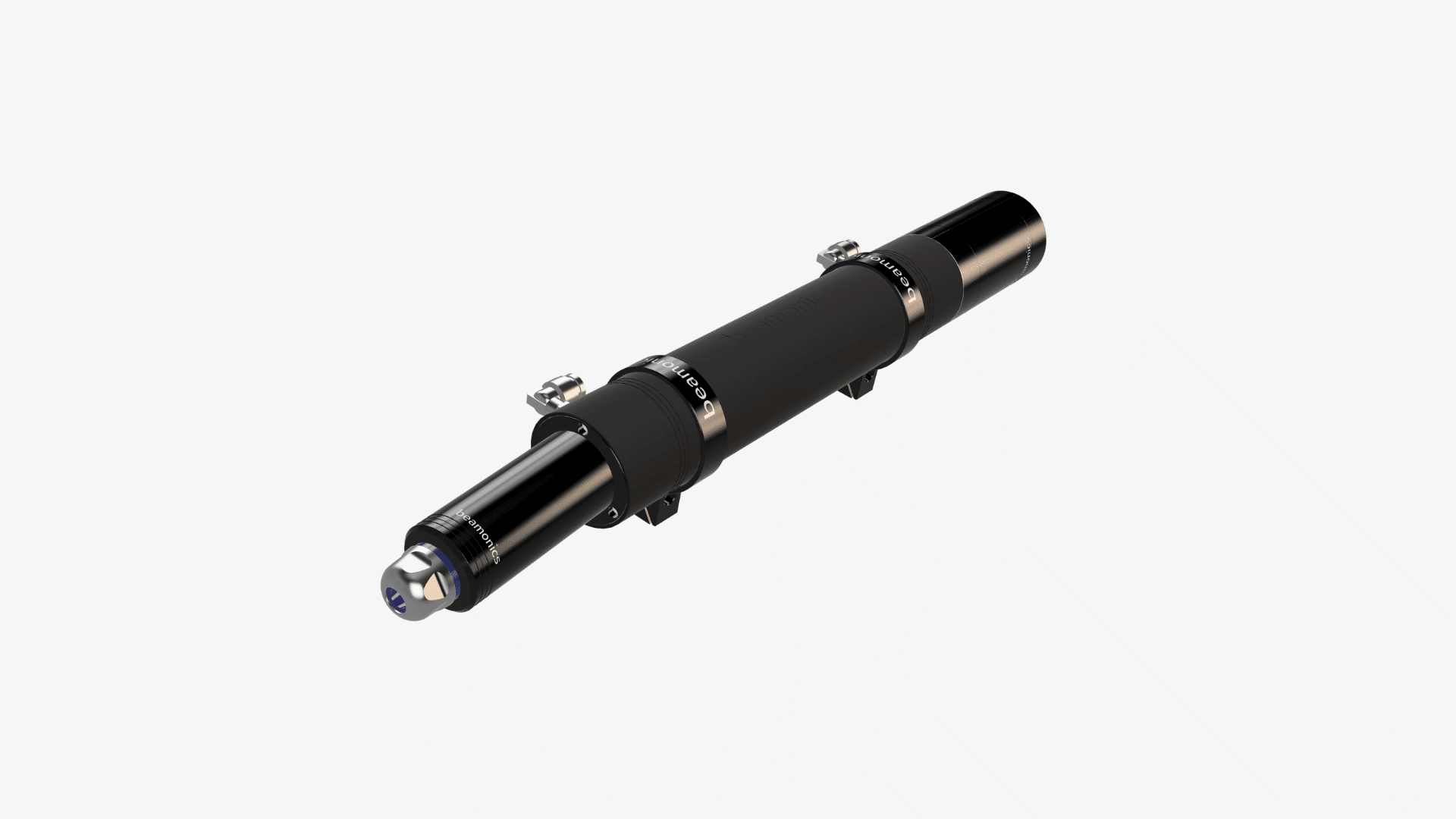
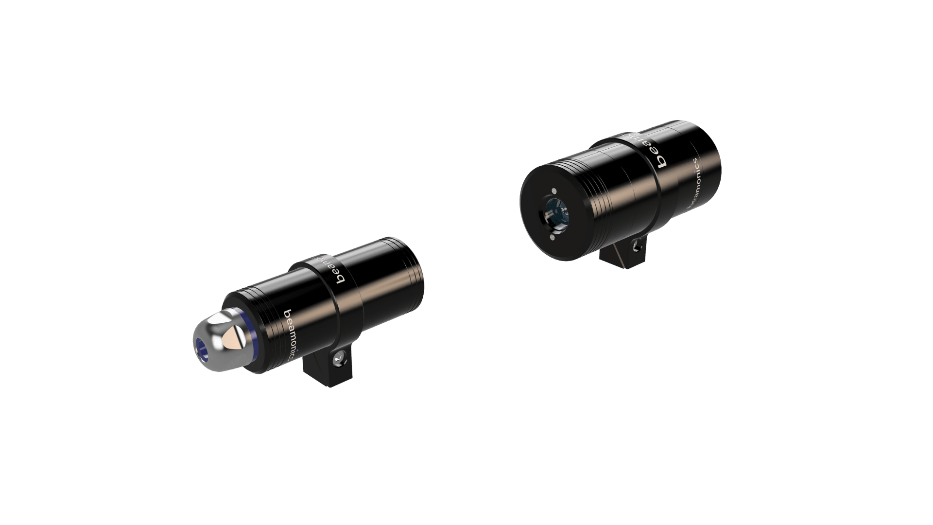
Beamonics BeamStack operates as a cross-stack analyzer, with transmitter and receiver mounted on opposite sides of the duct. The laser beam passes directly through the flue gas, measuring the path-averaged concentration across the full duct cross-section. There is no sample extraction, no transport delay, and no conditioning system. Under standard test conditions (1 m path length, 1 s averaging, 1 atm, 300 K), analysis precision reaches:
| Gas | BeamStack (1 m path) | BeamCell (0.185 m path) |
|---|---|---|
| CO | 0.2 ppm | 1 ppm |
| CO₂ | 0.5 ppm | 2.5 ppm |
| O₂ | 6 ppm | 30 ppm |
| H₂O | 0.2 ppm | 1 ppm |
| CH₄ | 0.2 ppm | 1 ppm |
| NH₃ | 0.2 ppm | 1 ppm |
These precision values are far below the concentration ranges relevant for power plant combustion control (O₂ at 2 to 8 vol%, CO at 10 to several hundred ppm, CO₂ at 4 to 15 vol%). The measurement margin means that small, control-relevant changes are clearly resolved against measurement noise.
Analysis rates up to 10 kHz allow BeamStack to capture transient combustion events, including load ramps, burner trips, soot blower operation, and fuel quality changes, as resolved events in the data rather than smoothed averages. For control system feedback, 1 to 10 Hz output is typical. For combustion diagnostics and event analysis, higher-rate data provides insight into flame dynamics and burner-to-burner variation.
The instrument is IP67-rated, operates from −10 °C to 55 °C, consumes 5 W, starts up in approximately 5 seconds, and connects to plant DCS via RS-485, 4-20 mA, and relay outputs.
Combustion optimization using multi-gas TDLAS data
Air-fuel ratio trim
The conventional approach to combustion optimization uses O₂ as the sole trim variable, with a setpoint chosen to balance efficiency against CO breakthrough. This works when the relationship between O₂ and CO is stable, but in practice that relationship shifts with fuel quality, burner condition, air register positions, and load level.
Adding CO measurement to the control loop provides a direct constraint: reduce excess air until CO begins to rise above a threshold (typically 50 to 200 ppm depending on fuel and boiler design), then hold at that point. This CO-trim approach keeps the combustion closer to the optimal point than O₂-trim alone because it responds to the actual combustion result rather than to an assumed O₂-to-efficiency relationship.
Adding CO₂ to the measurement set provides a cross-check. If CO₂ rises while O₂ falls and CO remains low, the combustion is moving toward optimal. If CO₂ falls while O₂ rises, excess air is increasing and efficiency is declining. If CO₂ falls while O₂ also falls, air ingress or a measurement fault should be investigated. The three gases together provide redundancy and diagnostic capability that no single gas offers alone.
Burner balancing and air distribution
In large boilers with multiple burners, combustion conditions can vary significantly from one burner to another. A burner with a restricted air register produces CO locally; a burner with excess air wastes energy locally. The overall flue gas measurement at the stack averages these variations, which means the plant may appear to be operating acceptably while individual burners are running far from optimal.
Cross-stack TDLAS measurement at multiple elevations or across individual burner rows can reveal these imbalances. Because each BeamStack installation is independent and provides real-time data, the control system can adjust air registers or fuel flow to individual burners based on their actual combustion performance rather than an assumed uniform distribution.
Load-following dynamics
Plants that cycle to follow variable renewable generation face more frequent load ramps than baseload operation. Each ramp changes the fuel input, air flow, and combustion dynamics. Slow analyzers report what the combustion looked like 30 to 60 seconds ago, which may correspond to a different load level than the current one. Beamonics TDLAS is a real-time technique with practically no response delay, meaning the control system sees the current state of the combustion at each moment during the ramp, allowing tighter control throughout the transient.
Emissions monitoring and reporting
CO₂ mass emissions from a power plant are calculated from the CO₂ concentration in the flue gas and the flue gas volumetric flow rate. For plants subject to emissions trading schemes or carbon reporting requirements, the accuracy of the CO₂ measurement directly affects the reported emissions and, potentially, the financial liability.
Beamonics TDLAS CO₂ measurement eliminates the drift-related uncertainty that accumulates between NDIR calibrations. A measurement that holds its accuracy over months without field recalibration provides greater confidence in the reported numbers, reduces the frequency of required reference audits, and simplifies the quality assurance procedures for continuous emissions monitoring systems (CEMS).
Instrument configurations for power plant applications
Cross-stack in-situ (BeamStack). The preferred configuration for combustion control measurement points where the duct geometry allows line-of-sight mounting. Measures CO, CO₂, O₂, and H₂O directly through the flue gas with no sample extraction. Suitable for the economizer exit, air heater outlet, or downstream of primary particulate control.
Extractive (BeamCell). Used when the measurement location has extremely high dust loading before particulate control, when duct geometry does not permit cross-stack mounting, or when multi-point measurement is required from a single analyzer. The acid-resistant flow chamber withstands exposure to SO₂ and other flue gas components. G1/8 push-in connectors accept 6 or 8 mm tubing. Multi-point valve sequencing allows cycling through several sample taps within seconds.
Stand-off (BeamSight). For survey-style assessment of stack emissions, temporary monitoring during commissioning, or screening of multiple stacks at a multi-unit plant without permanent installation. CO₂ detection precision of 40 ppm·m and CO detection precision of 15 ppm·m at 8 m range. The battery-powered portable version (1.0 kg, approximately 5 hours) supports rapid assessment of multiple emission points.
Practical Considerations
In coal-fired plants, the measurement location should be chosen to balance representativeness against exposure to particulate. Locations downstream of the air preheater but before the ESP offer representative combustion gas composition at moderate dust loading. Locations after the ESP have cleaner gas but may be influenced by air ingress through the precipitator casing. Beamonics instruments can handle transmission down to very low levels thanks to the proprietary platform, allowing processes to run uninterrupted without regular cleaning and re-calibration.
H₂O measurement by TDLAS provides direct moisture data that supports accurate emission calculations. Many regulatory frameworks require emissions to be reported on a dry-gas basis. Measuring H₂O alongside CO₂ and O₂ allows the dry-gas conversion to be performed using actual moisture data rather than an assumed or calculated value.
For natural gas-fired boilers, CO₂ concentrations are lower (typically 8 to 10 vol% at moderate excess air) and H₂O concentrations are higher (approximately 18 vol%) than for coal. The NDIR cross-interference problem from water vapor is more severe in gas-fired applications, which strengthens the case for TDLAS.
NH₃ measurement is relevant for plants equipped with selective catalytic or non-catalytic reduction (SCR/SNCR) for NOx control. NH₃ slip, the unreacted ammonia passing through the catalyst bed, must be monitored to prevent ammonium bisulfate deposition on downstream heat transfer surfaces and to comply with emission limits. BeamStack measures NH₃ at 0.2 ppm precision at 1 m, allowing NH₃ slip monitoring from the same cross-stack installation that provides combustion gas data.
Multiple gas measurements from a single cross-stack location require separate laser modules, each targeting a different absorption line. The Beamonics platform supports multi-gas configurations where the specific gas species and number of simultaneous channels are defined during system specification.
Closing Remark
Combustion optimization in power plants is a multi-variable control problem, and the gas analyzer provides the measurement variables. O₂, CO, and CO₂ each carry distinct information about the combustion process, and measuring all three with the speed, selectivity, and stability of Beamonics TDLAS gives the control system the data quality it needs to operate at the efficiency frontier. For plants facing tighter emissions constraints, higher cycling duty, and increasing fuel diversity, continuous multi-gas measurement is the foundation on which combustion performance and emissions performance are simultaneously maintained.