In Brief
Carbon monoxide is one of the most informative gases in cement and steel production. In cement kilns, CO tracks combustion quality in the rotary kiln and preheater tower, providing early warning of feed buildup, ring formation, and flame instability. In steelmaking, CO concentration in blast furnace top gas, basic oxygen furnace off-gas, and coke oven systems reflects reduction efficiency, carbon consumption, and leak conditions. Both industries operate at temperatures, dust loadings, and gas compositions that degrade conventional sensors within months. Beamonics TDLAS analyzers maintain measurement accuracy in these conditions without drift, cross-interference, or routine calibration, delivering the continuous real-time data that combustion control and safety interlocking depend on.
Background
Cement and steel plants share a fundamental characteristic: they are built around high-temperature chemical processes where carbon participates in both the fuel chemistry and the product chemistry. In cement production, carbon enters as kiln fuel (coal, petcoke, waste-derived fuels, natural gas) and as carbonate in the raw meal (CaCO₃ releasing CO₂ during calcination). In steelmaking, carbon enters as coke in the blast furnace, as injected coal or natural gas, and as carbon dissolved in the hot metal during oxygen blowing. CO appears wherever carbon oxidation is incomplete, whether in the combustion zone of a cement kiln or in the reduction zone of a blast furnace.
The significance of CO differs between the two industries, but in both cases the measurement requirements are demanding. Concentrations range from tens of ppm during stable operation to percent-level during process upsets. The gas matrix includes high CO₂ (up to 30 vol% in cement kiln exhaust, 20–25 vol% in blast furnace top gas), variable H₂O, and aggressive species including SO₂, HCl, alkali vapors, and heavy dust loading. Temperature at typical measurement locations ranges from 150 °C to over 400 °C depending on the process stage and plant configuration.
An analyzer that drifts between calibrations, responds too slowly to capture transient events, or loses accuracy when the background gas composition changes is not providing the data the control system needs. The consequences of poor CO data in these industries are specific and costly.
CO in cement production
Rotary kiln combustion control
The rotary cement kiln burns fuel at the hot end to produce the temperatures (1400 to 1500 °C in the burning zone) needed to convert raw meal into clinker. The fuel may be pulverized coal, petcoke, natural gas, or increasingly, alternative fuels such as refuse-derived fuel, waste tires, or solvents. Alternative fuels introduce additional variability in calorific value, moisture, and combustion behavior.
CO concentration in the kiln exhaust gas is the primary indicator of combustion completeness. During stable operation with adequate oxygen supply and good fuel-air mixing, CO sits at low levels. When combustion degrades, whether from a change in fuel quality, a shift in primary air flow, a buildup of clinker rings that disrupts the flame geometry, or a surge in raw meal feed that cools the burning zone, CO rises. The speed of that rise can be rapid: a kiln upset can produce a CO excursion from background to several hundred ppm within seconds.
Real-time CO data allows the kiln control system to respond proportionally. A moderate CO increase may call for increased induced draft fan speed to raise oxygen availability. A sharp spike may trigger a reduction in fuel feed rate or a temporary increase in kiln speed to clear a developing blockage. Without fast, accurate CO data, these adjustments happen reactively, after the problem has already affected clinker quality, refractory condition, or emission levels.
Preheater and calciner monitoring
Modern cement plants use a preheater tower with four to six cyclone stages to preheat the raw meal using kiln exhaust gas. Many plants also include a calciner, a secondary combustion chamber between the preheater and the kiln, where additional fuel is burned to drive the calcination reaction (CaCO₃ → CaO + CO₂). The calciner may consume 50 to 60% of the total fuel input.
CO monitoring in the preheater tower and at the calciner outlet serves multiple purposes. Rising CO in the preheater indicates that combustion conditions in the calciner or kiln are deteriorating, that volatile organic matter in the raw meal is being released, or that reducing conditions are developing in the lower cyclone stages. Reducing conditions promote the formation of low-melting-point compounds from sulfur and alkali species, which cause cyclone blockages and buildups that require costly shutdowns to clear.
In plants burning alternative fuels with variable and sometimes unpredictable combustion behavior, continuous CO monitoring at the calciner outlet is particularly important for maintaining stable calcination without allowing reducing conditions to develop.
CO and explosion prevention in cement plants
CO accumulation in the raw mill, preheater, or electrostatic precipitator (ESP) is a recognized explosion hazard in cement production. When CO reaches concentrations above the lower explosive limit in an enclosed space with a potential ignition source, the consequences are severe. ESP explosions caused by accumulated CO and combustible gases have resulted in significant equipment damage and production losses across the industry.
Many cement plants implement CO-based safety interlocks that trip the ESP or shut down sections of the process when CO exceeds defined thresholds. The reliability of these interlocks depends entirely on the CO analyzer. A sensor that drifts low over time may fail to trigger the interlock when needed. A sensor with a response time measured in minutes may detect the accumulation too late for the interlock to prevent an event. A sensor that produces false high readings from cross-interference with H₂O or CO₂ may trigger unnecessary shutdowns that cost production hours.
CO in steel production
Blast furnace top gas
In a blast furnace, coke and injected coal react with hot blast air to produce CO, which then reduces iron ore (Fe₂O₃) to metallic iron as it rises through the burden. The top gas leaving the furnace typically contains 20 to 25 vol% CO, 20 to 25 vol% CO₂, 2 to 5 vol% H₂, and the balance N₂. The CO-to-CO₂ ratio in the top gas is a direct indicator of furnace efficiency: a higher ratio means more CO is passing through unreacted, representing wasted reducing potential and excess coke consumption.
Continuous monitoring of CO in the top gas, together with CO₂ and H₂, allows the blast furnace operator to track the thermal state and reduction efficiency of the furnace. Changes in the CO/CO₂ ratio signal shifts in burden permeability, coke quality, or blast conditions before they manifest as changes in hot metal temperature or silicon content, which are slower-responding indicators.
Top gas is also a valuable fuel gas. It is cleaned, stored, and burned in hot blast stoves, power plant boilers, or coke oven gas mixing stations. Accurate CO measurement in the cleaned top gas supports combustion control in these downstream users and enables accurate calorific value calculation for fuel gas blending.
Basic oxygen furnace off-gas
In the BOF steelmaking process, pure oxygen is blown onto the surface of molten iron to oxidize dissolved carbon, producing CO that exits with the off-gas. The CO concentration in the off-gas follows a characteristic profile during the blow: it rises sharply as decarburization begins, plateaus during the main blow, and drops as the carbon content in the melt decreases toward the end point. Monitoring this CO profile in real time provides an indication of the progress of the blow and helps predict the end point, reducing the need for sub-lance sampling that interrupts the process.
The off-gas environment is extreme. Temperatures at the converter mouth exceed 1500 °C, and the gas carries heavy iron oxide dust. Measurement is typically performed downstream after initial cooling and dust removal, but even then the conditions are challenging for conventional sensors.
Coke oven gas and leak detection
Coke oven gas contains approximately 5 to 7 vol% CO along with H₂, CH₄, and various hydrocarbons. CO monitoring in the coke oven battery area, in by-product recovery systems, and around gas holders serves primarily as a safety measurement. Leaks from doors, lids, offtake pipes, and collector mains release CO into workspaces where personnel are present. Because CO is odorless and toxic, with an 8-hour occupational exposure limit of 20 to 35 ppm depending on jurisdiction, continuous monitoring is essential for worker protection.
Beamonics BeamSight is suited to this application. Stand-off measurement at distances up to 30 m (100 m with a reflector) allows CO monitoring across battery tops, along collector mains, and around gas holder perimeters without placing sensors in direct contact with the gas or in locations that are difficult to access for maintenance. Detection precision for CO is 15 ppm·m under standard test conditions (Range = 8 m, t = 0.5 s, P = 1 atm, T = 300 K). The battery-powered portable version (1.0 kg, approximately 5 hours of operation) supports walking surveys of the coke oven battery for leak identification and repair verification.
Why TDLAS is suited to these environments
Cement and steel plants share a set of measurement conditions that conventional CO sensors handle poorly.
High and variable CO₂ background. Cement kiln exhaust can contain up to 30 vol% CO₂, and blast furnace top gas contains 20 to 25 vol% CO₂. NDIR CO analyzers use broadband infrared absorption with optical filters, and the CO and CO₂ absorption bands overlap partially in the infrared. High CO₂ background introduces a cross-sensitivity that broadband compensation algorithms cannot fully correct when the CO₂ concentration itself is changing. Careful line selection is an inherent part of the Beamonics design process, and the analyzers as such offer little to no cross-interference. Beamonics TDLAS resolves the individual CO absorption line at a wavelength spectrally distinct from CO₂ features, so the CO reading is unaffected by the CO₂ background regardless of its concentration or variability.
Dust and particulate. Dust attenuates the laser beam, reducing the signal-to-noise ratio. TDLAS handles this because the measurement is based on the shape and depth of the absorption feature relative to the local baseline, following the Beer-Lambert law, not on the absolute intensity of the transmitted light. Beam attenuation from dust reduces total optical power but does not shift or distort the absorption line. Beamonics instruments can handle transmission down to very low levels thanks to the proprietary platform, allowing processes to run uninterrupted without regular cleaning and re-calibration.
Acid gases and alkali vapors. SO₂, HCl, and alkali compounds in the flue gas attack electrochemical sensor elements and deposit on optical surfaces. Electrochemical CO sensors exposed to these species experience accelerated drift and shortened life. TDLAS optics are non-consumptive. BeamCell’s acid-resistant flow chamber withstands exposure to aggressive gas mixtures in extractive configurations where sample conditioning removes gross particulate but the gas retains its chemical character.
Wide concentration range. CO may range from low-ppm to percent-level within the same process during different operating conditions. Beamonics TDLAS measures across this full range without mode switching, range selection, or dual-analyzer configurations, because the Beer-Lambert law describes a continuous relationship between absorption and concentration.
Real-time measurement. TDLAS is a real-time technique with practically no response delay. The optical measurement is instantaneous, with achievable time resolution governed by the analysis rate. BeamStack and BeamCell support analysis rates from 1 Hz to 10 kHz. A kiln upset that produces a CO spike lasting a few seconds is captured as a resolved transient event, providing the control system with the information it needs to respond before the upset progresses. Electrochemical sensors with T90 times of 30 to 90 seconds report these events as gradual undulations that do not convey the urgency of the actual concentration change.
Instrument selection
| Application | Recommended instrument | CO precision | Notes |
|---|---|---|---|
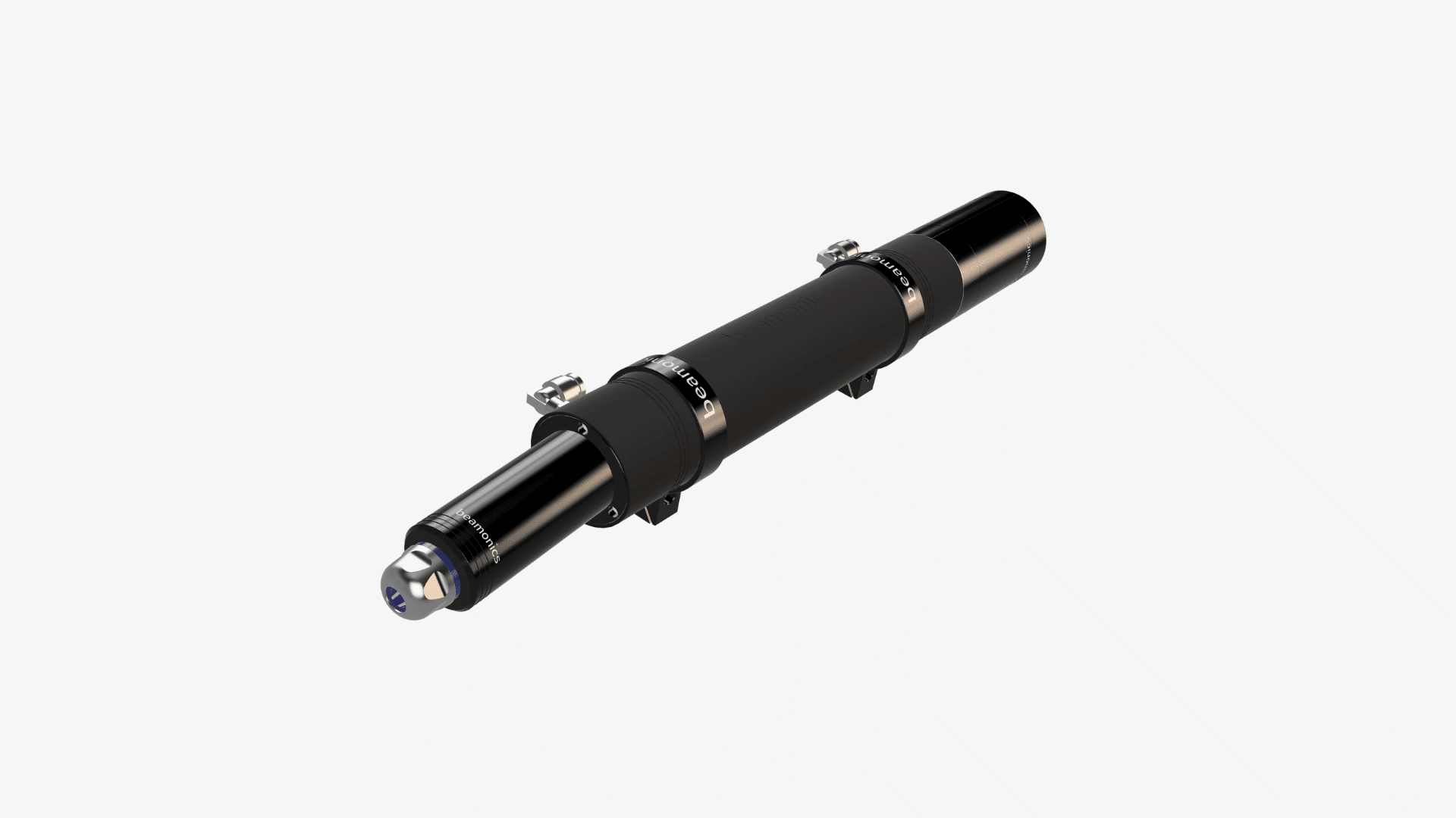
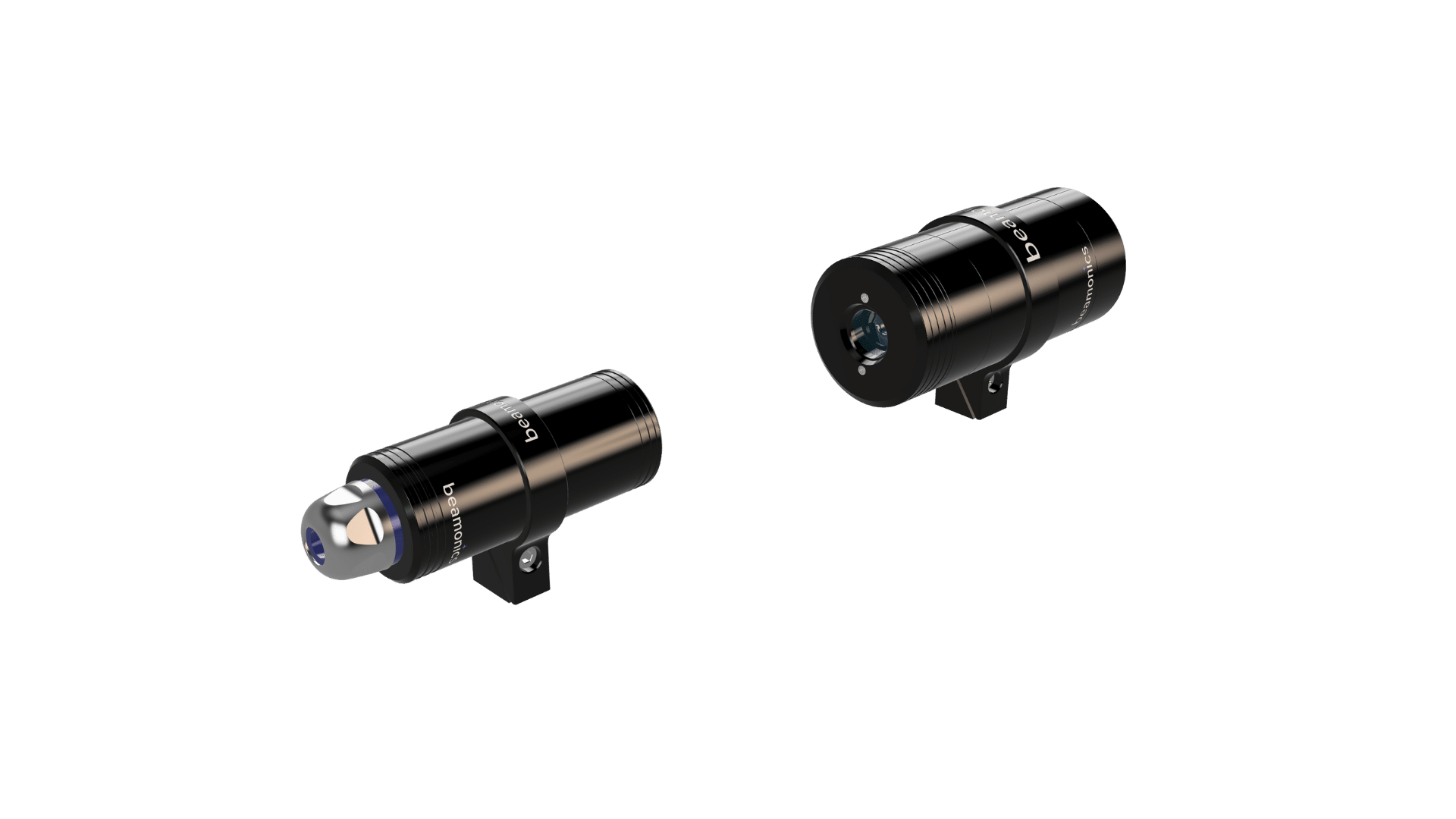
| Kiln exhaust, calciner outlet, preheater | BeamStack, cross-stack | 0.2 ppm (L = 1 m, t = 1 s) | In-situ, no sample extraction; IP67; −10 to 55 °C |
| ESP inlet monitoring for safety interlock | BeamStack, cross-stack | 0.2 ppm (L = 1 m, t = 1 s) | Real-time response for interlock reliability |
| BOF off-gas (after cooling and dust removal) | BeamCell, extractive | 1 ppm (L = 0.185 m, t = 1 s) | Acid-resistant flow chamber; multi-point option |
| Blast furnace top gas composition | BeamCell, extractive | 1 ppm (L = 0.185 m, t = 1 s) | Sequential sampling from multiple taps |
| Coke oven battery leak surveys | BeamSight, stand-off | 15 ppm·m (Range = 8 m, t = 0.5 s) | Portable; 30 m range; drone-mountable |
| Fence-line and area monitoring | BeamSight, stand-off | 15 ppm·m (Range = 8 m, t = 0.5 s) | Fixed or portable; 100 m with reflector |
All precision values under standard test conditions: P = 1 atm, T = 300 K. Largest of 1% relative and specified precision applies.
Practical considerations
Measurement location in a cement plant should be selected to provide representative combustion data while remaining accessible for periodic optical inspection. The preheater downcomer or the duct between the kiln and the preheater is a common location for combustion control. The ESP inlet is the standard location for explosion prevention interlocking. These are different control loops and may require separate analyzers. At Beamonics, we are experts on picking the path length for your specific measurement case. Please get in touch below.
In blast furnace top gas measurement, the gas is typically cleaned (by scrubber or dry dust catcher) before reaching the analyzer. Even after cleaning, the gas may carry residual moisture and fine particulate. Extractive sampling with upstream filtration protects BeamCell’s optics while the acid-resistant flow chamber handles the chemical composition.
Alternative fuels in cement production introduce additional CO variability. Waste-derived fuels with inconsistent calorific value and combustion behavior produce CO fluctuations that are larger and more frequent than those from conventional fossil fuels. The analyzer’s dynamic range must accommodate this increased variability without saturating during peaks or losing sensitivity during stable operation.
For safety-critical applications such as ESP interlocking, the analyzer should be configured with appropriate alarm logic including time delays, voting arrangements (if redundancy is used), and failsafe behavior on instrument fault. Beamonics TDLAS analyzers report explicit fault conditions when optical power, detector performance, or internal references fall outside normal operating bounds, which supports failsafe interlock design.
CO concentration in coke oven environments can vary from background levels to percent-level near active leaks. BeamSight’s measurement range from background atmospheric levels to saturation covers this span without reconfiguration.
Closing Remark
Cement kilns and steel furnaces are among the most demanding environments for gas analysis, combining extreme temperature, aggressive chemistry, heavy particulate, and wide concentration swings within a single process. CO is the measurement that ties combustion control, safety, and compliance together in both industries. The analyzer that provides this measurement must match the speed of the process, the complexity of the gas matrix, and the maintenance realities of a plant that operates continuously. Beamonics TDLAS meets these requirements by anchoring the measurement to molecular physics rather than to a sensor element that degrades under the conditions it is expected to monitor.