In Brief
The Beamonics product line covers three TDLAS measurement configurations: cross-stack (BeamStack), extractive (BeamCell), and remote stand-off (BeamSight). Each configuration has genuine strengths and genuine limitations. The right choice depends on the physical geometry of the measurement point, the gas species and concentration range, the required spatial information, and the practical constraints of installation and maintenance access.
Background
Selecting a gas analyzer is not only a question of which technology to use, but of how that technology interfaces with the process being measured. A TDLAS analyzer that performs well in one optical configuration may be poorly suited to another, not because the spectroscopy is different, but because the way light reaches the gas determines what the instrument can and cannot tell you.
The three Beamonics instruments share the same core TDLAS platform: the same laser modulation scheme, the same spectroscopy engine, and the same data interface architecture. What differs is the optical geometry, and that geometry determines the measurement’s spatial characteristics, its sensitivity to environmental interference, its installation requirements, and its practical limitations.
This article sets out what each configuration does well and where it falls short, so that the selection can be made on technical grounds rather than on product positioning.
BeamStack: cross-stack and open-path measurement
BeamStack places a transmitter on one side of a duct, pipe, or open space and a receiver on the other. The laser beam traverses the gas volume in situ, and the instrument reports the path-averaged gas concentration along the beam.
Where it works well
In-situ measurement eliminates the sample conditioning chain entirely: no heated lines, no filters, no pumps, no condensate drains. The gas is measured where it exists, at process temperature and pressure, without extraction delay. For combustion flue gases, duct emissions monitoring, or open-path perimeter monitoring, this is a direct and low-maintenance approach.
The path-averaged measurement captures the spatial mean along the beam, which reduces the influence of local concentration gradients and stratification compared to a single-point probe. In a 1 m duct, BeamStack provides O₂ precision of 6 ppm and CO precision of 0.2 ppm under standard test conditions (1 s averaging, 1 atm, 300 K). Analysis rates up to 10 kHz support applications involving rapid transients or turbulent mixing, such as combustion control or process upset detection.
The instrument is IP67-rated, consumes 5 W typical, operates from 15 to 32 VDC, and reaches measurement state within approximately 5 seconds of power-up.
Where it has limitations
The cross-stack configuration requires line-of-sight between the transmitter and receiver. This means two access points on opposite sides of the measurement volume, with mechanical mounting provisions (flanges, brackets, or process connections) at each. In retrofit installations where only one side of a duct is accessible, or where the duct geometry does not permit straight-through alignment, the configuration may not be feasible.
Dust, fog, and condensed water droplets in the beam path attenuate the laser signal. The instrument’s diagnostics monitor received optical power and report signal degradation as a fault rather than as a false concentration reading. Beamonics instruments can handle transmission down to very low levels thanks to the proprietary platform, allowing processes to run uninterrupted without regular cleaning and re-calibration.
The measurement is a path average along a single line. In large ducts with severe stratification, one beam line may not represent the full cross-sectional average. Multiple measurement paths or careful placement relative to mixing elements may be needed.
The transmitter and receiver are separate units connected by a cable, which adds to installation complexity compared to a single-point sensor. Alignment between the two is not difficult but must be maintained; thermal expansion of the duct or structural movement can require periodic re-alignment in some installations.
BeamCell: extractive flow-through measurement
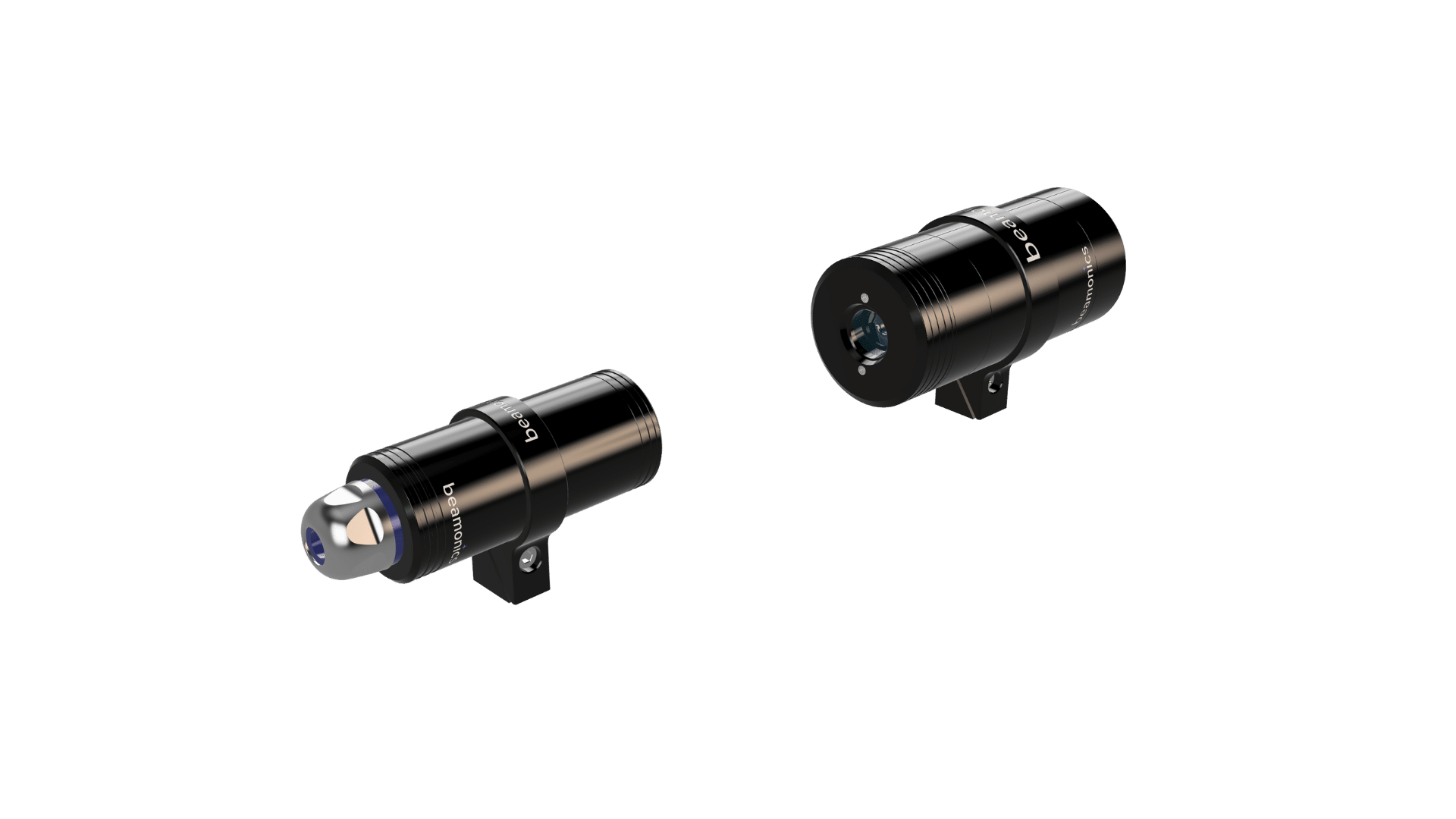
BeamCell draws gas from the process through a compact measurement cell with a 0.185 m optical path. The cell is fitted with push-in connectors (G1/8) for 6 or 8 mm tubing and is constructed from acid-resistant materials.
Where it works well
The extractive configuration decouples the measurement from the process geometry. The analyzer can be mounted in any convenient location, and the gas is brought to it via tubing. This suits applications where direct optical access across the process is not available: enclosed vessels, pressurised systems, locations with no second access point for a receiver, or sampling points inside equipment where an in-situ analyzer cannot be installed.
The controlled cell environment eliminates the influence of duct particulate, thermal gradients, and beam-path turbulence. For trace-level measurements where the precision floor matters, the extractive approach provides more repeatable conditions than an in-situ measurement through a dirty or thermally variable duct.
Multi-point sampling is a practical strength. A single BeamCell connected to a valve manifold can cycle through multiple sampling points sequentially. The instrument’s fast spectroscopy means that the switching time between points is limited by the valve actuation and sample purge time, not by the analyzer response. Even 16 sampling points can be covered within a few seconds.
The flow chamber withstands corrosive gases including sulfuric acid, which makes it suitable for applications in chemical processing, battery manufacturing, and acid-gas service where the sample would destroy conventional sensor elements.
O₂ precision is 30 ppm, CO precision is 1 ppm, and HF precision is 0.05 ppm at the 0.185 m path length under standard test conditions (1 s averaging, 1 atm, 300 K). The instrument shares BeamStack’s IP67 enclosure, interface set, and electrical characteristics.
Where it has limitations
Extractive measurement introduces a sample transport delay. The time between a concentration change at the sampling point and its detection at the analyzer depends on tubing length, tubing diameter, and flow rate. For applications where sub-second response at the process is required, this transport delay may be unacceptable.
The sample path requires maintenance. Tubing must be kept clear, and in corrosive or high-particulate service, filters upstream of the cell will need periodic replacement. Condensation in the sample line can block flow or dilute the sample if the gas cools below its dew point during transport. In applications with high moisture content or condensable species, heated sample lines or membrane dryers may be needed upstream of the cell.
The 0.185 m path length provides lower sensitivity than BeamStack’s longer in-situ paths. For gases where the absorption cross-section is small or where very low detection limits are needed, the shorter extractive path may not achieve the required precision. BeamStack at 1 m path length achieves roughly five times finer precision for most gases compared to BeamCell at 0.185 m.
The measurement is a point sample, not a spatial average. What enters the tubing is what gets measured, and the result reflects conditions at the sampling point only. Spatial variability across a duct or vessel is not captured unless multiple sampling points are used.
BeamSight: remote stand-off measurement
BeamSight detects gas at a distance by emitting a laser beam and analysing the light scattered back from whatever surface lies beyond the gas volume. No retroreflector or receiver on the far side is required.
Where it works well
The single-ended optical configuration is BeamSight’s defining advantage. There is nothing to install at the far end of the measurement path, no alignment between two separate units, and no cables crossing the monitored area. A single BeamSight can be pointed at different areas in sequence, or repositioned rapidly to survey a site. This suits leak detection, area monitoring over wastewater basins or tank farms, and mobile deployment on drones or rovers.
The instrument is compact (147 × 111 × 84 mm for the fixed version) and light (0.7 kg fixed, 1.0 kg with battery). The battery-powered portable version provides approximately 5 hours of operation, supporting handheld leak-searching sessions and drone-mounted survey flights without external power.
Detection precision for CH₄ is 15 ppm·m, for NH₃ 15 ppm·m, and for HF 0.05 ppm·m at 8 m range and 0.5 s averaging under standard conditions (1 atm, 300 K). The instrument can detect atmospheric background concentrations of several gases, which means it can identify elevated concentrations above background with high confidence.
Interfaces include Mini USB, I²C, UART, and GPIO. The IP44-rated enclosure suits both fixed outdoor installations and handheld field use. Power consumption is under 5 W.
Where it has limitations
The measurement unit is ppm·m (concentration integrated over path length), not ppm. Converting to a point concentration requires knowledge of the gas distribution along the beam path, which is rarely available in practice. BeamSight reports how much absorption occurred along the measurement path, but it cannot distinguish between a thin, high-concentration plume and a diffuse, low-concentration cloud that produces the same integrated absorption.
Detection range extends to 30 m using natural diffuse back-reflections, or up to 100 m with a reflecting surface. Signal-to-noise ratio decreases with distance because the back-scattered light intensity falls off with range. At the maximum detection distance, precision degrades and the minimum detectable concentration-path-length product increases. Performance specifications are stated at 8 m range; sensitivity reduces at longer distances.
The back-scatter signal depends on the reflectivity of the surface behind the gas. Dark, absorptive, or wet surfaces return less light than bright, diffuse surfaces, which affects the achievable signal-to-noise ratio. In practice, the operator may need to select measurement paths that terminate on suitable surfaces.
BeamSight’s IP44 rating provides protection against solid objects larger than 1 mm and water splashing from any direction, but it is not rated for immersion or heavy washdown, unlike the IP67-rated BeamStack and BeamCell. For permanent outdoor installations in exposed locations, additional weather protection may be needed.
The battery life of 5 hours in the portable configuration limits continuous field use. The fixed-installation version operates on external power (9 to 24 VDC) and does not have this constraint.
The gas species list differs from the other products. BeamSight currently supports CH₄, CO₂, CO, HF, H₂S, and NH₃. It does not cover O₂, H₂O, HCl, or N₂O, which are available on BeamStack and BeamCell.
Selecting a configuration
The choice between the three configurations is driven by a few practical questions.
Is there optical line-of-sight across the measurement volume, with access on both sides? If yes, BeamStack provides the most direct, lowest-maintenance measurement with the highest sensitivity per unit path length.
Is the gas accessible only via a sampling point, or does the application require multi-point measurement from a single analyzer? BeamCell serves these cases, at the cost of sample transport delay and a shorter optical path.
Is the goal to detect and localise gas at a distance, without installing anything at the measurement point? BeamSight is the appropriate tool, with the understanding that the measurement is path-integrated (ppm·m) rather than volumetric (ppm).
Some applications benefit from combining configurations. A BeamStack across a process duct for continuous in-situ monitoring, paired with a BeamSight for periodic leak surveys around the facility perimeter, uses each instrument where its configuration is strongest.
Closing Remark
Every measurement configuration involves trade-offs. Stating them clearly, including the limitations of the instruments being discussed, is more useful to the engineer making a selection decision than a feature list that implies universal suitability. The specifications and constraints described here are intended to support that decision with technical substance.