In Brief
Waste incineration produces CO concentrations that fluctuate rapidly and unpredictably because the fuel, municipal or industrial waste, varies in composition, moisture, and calorific value from one load to the next. Continuous CO monitoring serves three functions simultaneously: it provides the combustion control signal needed to maintain efficient burnout, it guards against explosive CO accumulation in downstream ductwork, and it satisfies the continuous emissions monitoring requirements imposed by most regulatory frameworks. Beamonics TDLAS analyzers are well suited to this application because they maintain accuracy in the high-dust, high-moisture, chemically aggressive exhaust environment that defines waste incineration, without the drift, cross-interference, and consumable replacement cycle of conventional CO sensors.
Background
Waste-to-energy plants combust heterogeneous fuel. Unlike natural gas or coal, which have relatively stable composition, municipal solid waste varies in moisture content, plastic fraction, organic load, and inert material from hour to hour and sometimes from minute to minute. A batch of wet garden waste followed by dry packaging material changes the combustion conditions inside the furnace significantly: flame temperature shifts, oxygen demand changes, and the completeness of carbon oxidation fluctuates accordingly.
Carbon monoxide is the most direct chemical indicator of these combustion variations. In complete combustion, carbon in the fuel reacts with oxygen to form CO₂. When oxygen is insufficient, when mixing is poor, when the fuel bed is too wet to sustain flame temperature, or when the residence time at high temperature is too short, the oxidation stops at CO instead of proceeding to CO₂. The CO concentration in the exhaust therefore reflects the instantaneous quality of the combustion process.
The concentrations involved span a wide range. During stable operation with well-mixed, moderate-moisture waste, CO levels in the flue gas may sit in the single-digit to low tens of ppm. During a feed disruption, a wet slug entering the furnace, or a grate malfunction that disrupts the fuel bed, CO can spike to hundreds or thousands of ppm within seconds. These transients are not anomalies to be filtered out of the data. They are the events that matter most for all three purposes of CO monitoring.
For combustion control, a CO spike signals that the air supply, grate speed, or feed rate needs adjustment. For safety, sustained elevated CO in enclosed ductwork downstream of the furnace can approach the lower explosive limit (12.5 vol% in air), particularly in zones where the gas has cooled below ignition temperature but has not yet been diluted. For compliance, emission permits typically specify both time-averaged and short-term CO limits, and the ability to detect and document short exceedances is a regulatory requirement, not an operational preference.
The waste incineration exhaust environment
The flue gas downstream of a waste incinerator is one of the more demanding measurement environments in industrial gas analysis. Understanding the specific challenges explains why certain analyzer technologies perform poorly here and why others are better matched.
Particulate loading is substantial. Waste combustion produces fly ash and entrained particulate at concentrations that can reach several grams per cubic meter upstream of the particulate control system. Any optical measurement through this gas must tolerate significant beam attenuation while still extracting a reliable absorption signal. Any sensor element in direct contact with the gas stream, such as an electrochemical cell or catalytic bead, is exposed to abrasive particles and chemical deposits.
Flue gas from waste incineration typically carries 10 to 20 vol% H₂O, depending on waste moisture content. High and variable moisture concentration is a source of cross-interference for broadband infrared measurement techniques and contributes to condensation risks in sample transport systems.
Municipal waste contains chlorine (from PVC and other plastics) and sulfur (from organic matter and textiles). Combustion produces HCl and SO₂ at concentrations that range from tens to hundreds of ppm before flue gas treatment. These are corrosive to many sensor materials and metallic surfaces. HF may also be present from fluorinated materials in the waste stream.
Flue gas temperatures at the measurement point vary depending on location in the system. Upstream of the boiler, temperatures may exceed 800 °C. At typical measurement locations downstream of heat recovery but upstream of the flue gas treatment system, temperatures are commonly in the 150 to 300 °C range. Downstream of the scrubber, gas may be near saturation temperature with high relative humidity.
Beyond CO, the exhaust contains CO₂ at 8 to 14 vol%, O₂ at 6 to 12 vol%, N₂ as the balance gas, and varying concentrations of HCl, SO₂, NOx, NH₃ (if reagent injection is used), and volatile organic compounds. Any CO measurement technique must produce accurate results despite these background gases.
Why conventional CO sensors struggle in incineration
Electrochemical CO sensors placed in this environment face multiple challenges simultaneously. Electrolyte aging is accelerated by elevated temperature and exposure to acid gases. H₂ and H₂S, both present in reducing zones of incineration exhaust, produce cross-interference that inflates the apparent CO reading. Response times (T90) of 30 to 90 seconds mean that a 10-second CO spike during a feed disturbance is either missed entirely or reported as a gentle rise and fall that understates the true peak. Sensor poisoning from HCl, SO₂, and silicone compounds shortens usable life. The practical result is an instrument that drifts between calibrations, misses transient events, and requires frequent maintenance in an environment where access to the measurement point may be restricted by temperature, confined-space protocols, or ongoing operations.
NDIR analyzers offer better stability than EC sensors but remain susceptible to interference from H₂O and CO₂, both of which are present at high and variable concentrations in incineration exhaust. Because NDIR measures absorption across a relatively broad infrared band defined by an optical filter, it cannot fully separate the CO absorption from overlapping absorption by H₂O. Compensation algorithms correct for this to some degree, but the correction depends on knowing the H₂O concentration accurately, which is itself variable. Extractive NDIR systems also require sample conditioning (filtration, drying, sometimes dilution) to protect the measurement cell and reduce interference, adding transport delay, maintenance burden, and potential sample loss for reactive species.
TDLAS for CO measurement in waste incineration
TDLAS addresses each of these challenges through its measurement principle. A narrowband laser is scanned across a single CO absorption line that is spectrally distinct from the absorption features of H₂O, CO₂, HCl, SO₂, and other exhaust gas components. The line is resolved individually, not approximated through a broadband filter. Careful line selection is an inherent part of the Beamonics design process, and the analyzers as such offer little to no cross-interference from background gases in incineration exhaust.
The self-referencing nature of the measurement, where each laser scan establishes its own baseline by covering both absorbing and non-absorbing wavelength regions, eliminates the drift that accumulates in sensors relying on chemical reactions or broadband reference channels. The CO reading after six months of continuous operation is referenced to the same molecular absorption physics, described by the Beer-Lambert law, as the reading on the first day.
TDLAS is a real-time technique with practically no response delay. The optical measurement is instantaneous, with the achievable time resolution governed by the analysis rate. Beamonics BeamStack supports rates from 1 Hz to 10 kHz, which means a CO spike lasting 100 milliseconds during a grate upset is captured as a resolved event. This is the data that combustion control systems need to adjust air supply and feed rate, that safety systems need to trigger interlocks before CO accumulates to hazardous levels, and that compliance records need to document whether short-term emission limits were exceeded.
There are no consumable sensor elements to replace, no electrolyte to replenish, no reference gas bottles to schedule. The instrument monitors its own optical power, detector performance, and internal references, and reports explicit fault conditions. A degraded measurement appears as a diagnostic alarm, not as a false CO reading.
Instrument selection for waste incineration CO monitoring
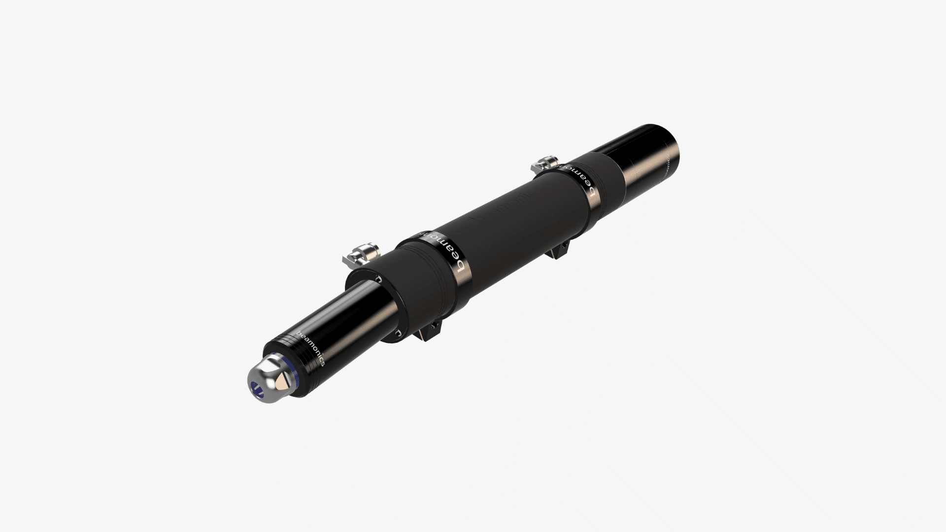
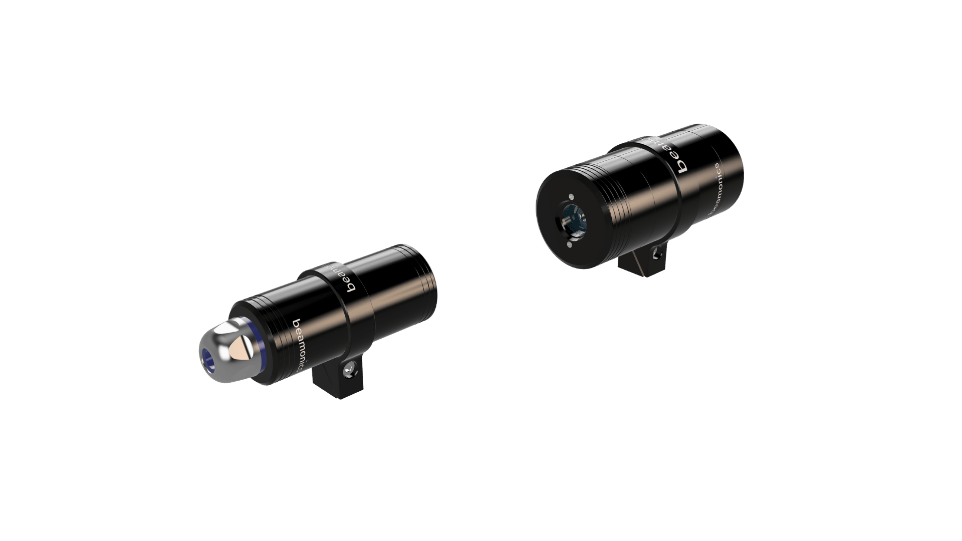
Cross-stack in-situ installation. BeamStack, mounted as a transmitter-receiver pair across the flue gas duct, measures CO directly through the exhaust stream. No sample is extracted, no conditioning is required, and there is no transport delay. The laser beam traverses the full duct cross-section, providing a spatially representative path-averaged concentration. Under standard test conditions (L = 1 m, t = 1 s, P = 1 atm, T = 300 K), CO analysis precision is 0.2 ppm. The IP67 enclosure operates from −10 °C to 55 °C. Standard PLC interfaces (RS-485, 4–20 mA, relay outputs) connect to the plant’s distributed control system for combustion optimization and safety interlocking.
For waste incineration applications, in-situ cross-stack installation is generally preferred when the measurement location offers suitable mounting points on both sides of the duct. At measurement locations downstream of primary particulate removal (for example, after a cyclone but before the baghouse), dust loading is typically compatible with reliable in-situ operation. Beamonics instruments can handle transmission down to very low levels thanks to the proprietary platform, allowing processes to run uninterrupted without regular cleaning and re-calibration.
Extractive sampling. When the measurement point is located in a high-dust zone upstream of any particulate control, or when the duct geometry does not permit line-of-sight mounting, BeamCell provides CO measurement through a compact extractive flow cell. The acid-resistant chamber (0.185 m optical path) withstands exposure to HCl, SO₂, and other corrosive species in incineration exhaust. CO precision under standard conditions (L = 0.185 m, t = 1 s, P = 1 atm, T = 300 K) is 1 ppm. Sample filtration upstream of the cell removes particulate, and heated sample lines prevent condensation in the tubing. BeamCell also supports multi-point sampling via valve manifold, which allows a single instrument to monitor CO at several points in the process, such as before and after the flue gas treatment system, providing real-time data on both combustion performance and treatment system effectiveness.
Additional gases. Waste incineration facilities typically need to monitor several gases beyond CO. HCl, SO₂, NOx, NH₃, H₂O, O₂, and CO₂ are all relevant for process control or compliance. The Beamonics TDLAS platform covers HCl, HF, NH₃, H₂S, H₂O, O₂, CO₂, and CH₄ in addition to CO, depending on the laser module configuration. Separate analyzers targeting different absorption lines can operate in parallel to provide a multi-gas monitoring solution using a consistent measurement technology.
CO monitoring as a combustion control and safety input
In a waste incineration control system, CO data serves multiple functions simultaneously.
Primary air and grate speed control. When CO rises because a wet slug of waste has entered the furnace and depressed the flame temperature, the control system can respond by increasing primary air flow to supply more oxygen, adjusting grate speed to improve fuel bed mixing, or temporarily reducing the feed rate. Without fast CO feedback, these adjustments happen too late, after the combustion quality has already degraded enough to affect downstream equipment and emission levels.
Secondary air optimization. CO remaining above the fuel bed is oxidized in the secondary combustion zone by injecting additional air. The CO concentration leaving the secondary zone indicates whether the air injection is sufficient. Over-injection wastes energy by heating excess nitrogen. Under-injection allows CO and unburned organics to pass through to downstream equipment. Real-time CO measurement at the secondary zone outlet closes this control loop.
Furnace safety interlocks. In some plant designs, CO concentration in the flue gas duct is used as an input to safety interlock logic. If CO exceeds a defined threshold and remains elevated, the system can initiate protective actions such as increasing dilution air, shutting down auxiliary fuel injection, or in extreme cases triggering an emergency shutdown. The interlock depends on the CO measurement being both fast and reliable: fast enough to detect a real accumulation event before it reaches a dangerous level, and reliable enough that the interlock is not triggered by sensor drift or cross-interference.
Compliance averaging and peak reporting. Emission permits for waste incineration facilities typically specify a half-hourly or hourly average CO limit and may also include a short-term (for example, 10-minute) limit. Meeting these requirements means logging continuous CO data at sufficient resolution to compute both the average and the short-term peaks accurately. A slow sensor that smooths over transient spikes will underreport the true short-term maximum, which creates a compliance documentation gap even if the actual emissions were within limits.
Practical considerations
The wide dynamic range of CO in waste incineration, from low-ppm during good combustion to thousands of ppm during upsets, requires an analyzer that does not saturate or lose accuracy at high concentrations. Beamonics TDLAS handles this range inherently because absorption and concentration are related through the Beer-Lambert law across the full range, without requiring manual range switching.
Measurement location selection matters. Placing the analyzer too close to the furnace exposes it to extreme temperature and heavy particulate. Placing it too far downstream, after flue gas treatment, provides a CO reading that reflects the entire system rather than the combustion process specifically. The ideal location for combustion control is typically after primary heat recovery but before flue gas treatment, where the gas is representative of combustion conditions but has cooled enough for practical instrumentation. At Beamonics, we are experts on picking the path length for your specific measurement case. Please get in touch below.
For facilities burning hazardous or clinical waste, additional gas species (HF, heavy metals, dioxin precursors) may be subject to monitoring requirements. While TDLAS does not measure dioxins or metals directly, the CO and O₂ data it provides are standard surrogate parameters used in many regulatory frameworks to demonstrate that combustion conditions are sufficient to destroy organic pollutants.
Closing Remark
Waste incineration is a combustion process defined by fuel variability, and CO is the signal that tracks how well the combustion system is handling that variability at any given moment. The measurement must be fast enough to capture the transient spikes that characterize feed disturbances, selective enough to avoid false readings in a complex and corrosive exhaust matrix, and stable enough to maintain accuracy across months of continuous operation without recalibration. Beamonics TDLAS meets all three requirements through a measurement principle that is referenced to molecular physics rather than to a degrading sensor element, in an instrument designed for the conditions that waste incineration actually presents.