In Brief
Carbon capture and storage requires gas analysis at every stage of the process: measuring CO₂ removal efficiency at the capture plant, monitoring trace impurities in transport pipelines, and detecting leaks at storage sites over timescales of decades. The concentrations span six orders of magnitude, from near-pure CO₂ in transport to parts-per-million changes against atmospheric background at storage perimeters. TDLAS-based analyzers cover this range with a measurement that does not drift, does not cross-react with co-present gases, and requires no routine field calibration, addressing the central reliability problem that limits conventional sensors in long-duration CCS deployments.
Background
CCS is a process chain, not a single operation. CO₂ is separated from an industrial source (power plant flue gas, cement kiln exhaust, hydrogen production off-gas, steel plant blast furnace gas), compressed, transported by pipeline or ship, and injected into a geological formation for permanent storage. Each link in this chain has distinct gas analysis requirements, and a failure at any point, whether a missed impurity in the transport stream, an undetected efficiency drop at the capture plant, or an overlooked surface leak at the storage site, undermines the integrity of the entire system.
The gas analysis challenges reflect this diversity. At the capture plant, the analyzer operates in hot, humid flue gas containing CO₂ at 4 to 15 vol% alongside H₂O, N₂, O₂, SO₂, and NOx, and must also measure the treated gas leaving the absorber where CO₂ may be below 1 vol%. In the transport pipeline, the gas is nearly pure CO₂ at high pressure, and the analytical concern shifts from measuring CO₂ itself to detecting trace contaminants, H₂O, H₂S, O₂, and non-condensable gases, that cause corrosion, hydrate formation, or two-phase flow problems. At the storage site, the task reverses again: detecting small CO₂ concentration increases against the natural atmospheric background of approximately 420 ppm, potentially over areas of several square kilometers and over monitoring periods measured in decades.
No single conventional analyzer technology handles all of these roles well. NDIR analyzers measure CO₂ effectively at percent levels but suffer cross-interference from water vapor and lose accuracy at very low concentrations. Electrochemical sensors for H₂S and O₂ drift over time and degrade in the presence of the acid gases and amine residues found in capture plant streams. Point sensors placed at fixed locations around a storage site provide coverage only at their specific positions and require ongoing calibration and sensor replacement.
TDLAS provides a consistent measurement approach across the chain. The same physical principle, scanning a laser across a molecular absorption line and measuring the resulting attenuation, applies whether the target is CO₂ at 12 vol% in flue gas, H₂O at 50 ppm in a transport pipeline, or CO₂ at 40 ppm·m above background at a storage perimeter. The selectivity comes from the absorption line itself, which is unique to each molecular species. The stability comes from the self-referencing measurement, where each laser sweep establishes its own baseline. The result is an analyzer that holds its accuracy without field recalibration, which is not a convenience but a practical necessity for infrastructure that must operate reliably for years with minimal maintenance access.
Capture plant measurement
Post-combustion capture using amine solvents is the most commercially mature CCS technology. Flue gas enters the bottom of an absorber column and flows upward through a packed bed countercurrent to a descending amine solution that chemically binds the CO₂. The treated gas, now depleted in CO₂, exits the top of the absorber. The CO₂-rich solvent is pumped to a stripper column where heat regenerates the amine and releases concentrated CO₂ for compression.
The capture plant operator needs to know the CO₂ concentration at three key points: the absorber inlet (raw flue gas), the absorber outlet (treated gas), and the stripper outlet (concentrated CO₂ product). The difference between inlet and outlet CO₂ determines capture efficiency. The stripper outlet composition defines the quality of the CO₂ being sent for compression and transport.
These measurement points present different analytical challenges. The absorber inlet gas is hot, humid, and may contain SO₂ residues and particulate from upstream flue gas treatment. The absorber outlet gas has been in intimate contact with the amine solvent and may carry amine mist or degradation products that foul sensor surfaces. The stripper outlet is a concentrated CO₂ stream at elevated temperature with trace water and amine vapors.
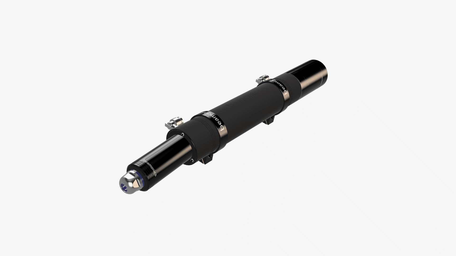
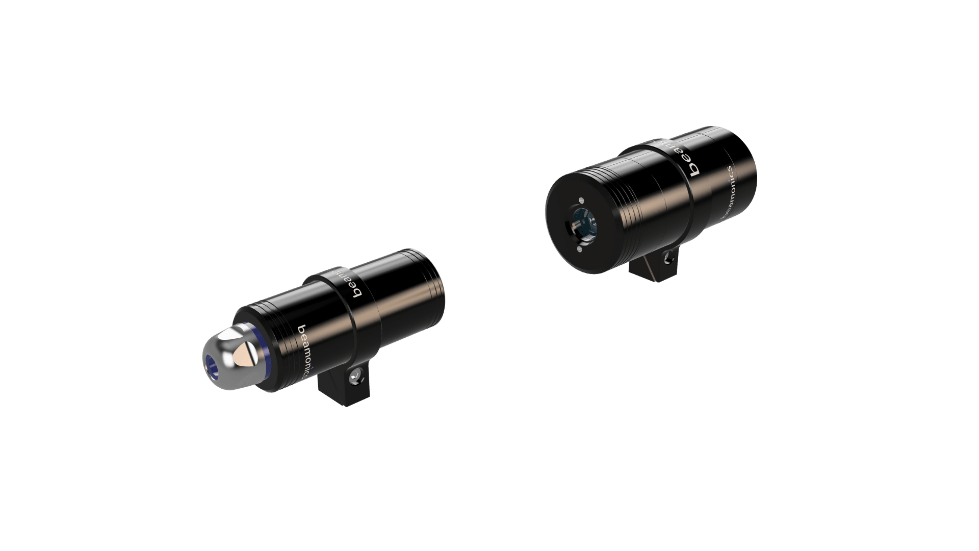
The Beamonics BeamCell (BM-H-3) is configured for extractive measurement in these conditions. Its acid-resistant flow chamber tolerates exposure to amine-laden and acidic gas streams. Push-in G1/8 connectors accept 6 or 8 mm tubing for connection to sample probes at each measurement point. Multi-point valve sequencing allows a single analyzer to cycle through the absorber inlet, absorber outlet, and other process taps within seconds, providing near-simultaneous concentration data from multiple locations.
Under standard test conditions (0.2 m path length, 1 s averaging, 1 atm, 300 K), the BeamCell achieves CO₂ precision of 2.5 ppm. This is far below the concentration resolution needed to track capture efficiency: detecting a change from 90% to 89% capture on a flue gas entering at 12 vol% CO₂ requires resolving a change at the absorber outlet from approximately 1.2 vol% to 1.32 vol%, a difference of roughly 1200 ppm. The 2.5 ppm precision provides substantial margin. Analysis rates up to 10 kHz allow the analyzer to track process dynamics during solvent flow changes, temperature adjustments, or flue gas composition shifts, providing feedback fast enough for closed-loop control of the capture process.
For cross-stack measurement across the absorber inlet duct or across the flue gas path upstream of the capture plant, the BeamStack (BM-H-3) provides in-situ CO₂ measurement at 0.5 ppm precision (1 m path length, 1 s averaging). The in-situ configuration eliminates sample lines, transport delay, and the risk of CO₂ adsorption or amine condensation in tubing. IP67 enclosures and operation from −10 °C to 55 °C allow permanent outdoor installation on ductwork.
Transport pipeline monitoring
After capture, CO₂ is dehydrated, compressed to a dense or supercritical phase (typically above 80 bar), and transported by pipeline. The CO₂ stream at this stage is 95 to 99.5% pure depending on the capture technology and the pipeline specification. The analytical focus shifts from measuring CO₂ concentration to measuring the impurities that threaten pipeline integrity and injection well performance.
Water (H₂O). The most critical impurity in CO₂ transport. Free water in dense-phase CO₂ forms carbonic acid, which is severely corrosive to carbon steel pipeline material. Water also promotes hydrate formation with CO₂ at the pressures and temperatures found in pipelines, potentially blocking flow. Pipeline specifications typically limit H₂O to 50 to 500 ppm depending on the operator and material grade. The BeamStack achieves H₂O precision of 0.2 ppm at a 1 m path length under standard conditions, providing clear resolution against these thresholds.
Hydrogen sulfide (H₂S). Present in CO₂ captured from sources with sulfur-containing fuel or feedstock. H₂S causes sulfide stress cracking in pipeline steel, particularly at the higher partial pressures found in dense-phase CO₂ transport. Pipeline H₂S limits are typically below 10 to 200 ppm depending on steel grade and operating conditions. The BeamStack provides H₂S precision of 0.3 ppm at 1 m.
Oxygen (O₂). Oxygen in the CO₂ stream accelerates corrosion, particularly in combination with water. O₂ limits in pipeline specifications are typically 10 to 100 ppm. The BeamStack achieves O₂ precision of 6 ppm at 1 m.
Non-condensable gases (N₂, Ar, H₂). These affect the phase behavior of the CO₂ stream, reducing the density and potentially causing two-phase flow at conditions where pure CO₂ would remain in dense phase. While TDLAS does not measure N₂ or Ar (they lack usable near-infrared absorption lines), it provides selective measurement of the species that do have strong absorption features, and the presence of non-condensables can be inferred from process measurements of density and pressure.
For pipeline monitoring, the key advantage of TDLAS is selectivity in a high-CO₂ background. Measuring 100 ppm of H₂O in a matrix that is 99% CO₂ is a severe challenge for broadband infrared techniques because CO₂ itself absorbs broadly across the mid-infrared. TDLAS resolves the individual H₂O or H₂S absorption line at a wavelength chosen to be free of CO₂ interference, so the background matrix concentration has no effect on the impurity measurement.
Storage site monitoring
Geological CO₂ storage sites must be monitored to confirm that injected CO₂ remains in the target formation and is not migrating to the surface through faults, abandoned wells, or caprock imperfections. Surface monitoring typically involves measuring atmospheric CO₂ concentrations across the storage site footprint and comparing them to background levels and natural variability.
The measurement challenge is detecting a small, potentially localized CO₂ signal against natural background variation. Atmospheric CO₂ fluctuates diurnally and seasonally by tens of ppm due to photosynthesis, soil respiration, and meteorological mixing. A storage leak might produce a surface signal of similar magnitude, distributed over a limited area and potentially intermittent depending on atmospheric conditions.
The Beamonics BeamSight (BM-V-2) addresses this with remote stand-off measurement. Pointed at the ground surface or a nearby structure, it measures path-integrated CO₂ concentration along the beam in ppm·m, with detection precision of 40 ppm·m under standard test conditions (10 m range, 0.5 s averaging, 1 atm, 300 K). Detection range extends to 30 m in free space and up to 100 m with a reflective surface.
For storage site monitoring, several deployment strategies are relevant:
Fixed perimeter monitoring. Multiple BeamSight units installed on posts around the site boundary provide continuous surveillance of the areas most likely to exhibit leakage, such as above known faults or near abandoned wells. The path-integrated measurement is inherently sensitive to broad, low-concentration plumes that point sensors placed between mounting locations might miss.
Drone-mounted surveys. The battery-powered portable BeamSight (1.0 kg, approximately 5 hours battery life) mounted on a drone can survey the entire storage site footprint systematically. Gridded flight patterns produce a spatial map of CO₂ concentration across the site, identifying areas of elevated concentration that warrant closer investigation. This approach covers large areas efficiently without permanent infrastructure across the site.
Walking surveys and verification. Handheld BeamSight supports focused investigation of areas flagged by fixed monitors or drone surveys. The operator points the instrument at the ground from several angles and distances to localize and characterize a suspected seep.
The distinction between ppm·m (path-integrated concentration) and ppm (point concentration) is important for storage monitoring. A BeamSight reading of 200 ppm·m along a 10 m beam could represent a uniform 20 ppm enhancement across the full path, or a concentrated seep at 200 ppm crossing 1 m of the beam. Interpreting the data requires knowledge of the measurement geometry, which scanning from multiple angles provides. For quantitative flux estimation, concentration data must be combined with wind speed measurements and dispersion modeling.
Storage site monitoring programs are designed for decades of operation. TDLAS optical components have expected lifetimes in the 10-year range when operated within specifications. The self-referencing measurement does not accumulate drift over time, so a reading taken ten years after installation is referenced to the same molecular physics as the initial measurement. This long-term stability is fundamental to the credibility of storage site monitoring data.
Specification overview
| Parameter | BeamCell (BM-H-3) | BeamStack (BM-H-3) | BeamSight (BM-V-2) |
|---|---|---|---|
| Measurement type | Extractive | Cross-stack / open-path | Remote stand-off |
| CO₂ precision | 2.5 ppm | 0.5 ppm | 40 ppm·m |
| CO precision | 1 ppm | 0.2 ppm | 15 ppm·m |
| H₂S precision | 1.5 ppm | 0.3 ppm | 25 ppm·m |
| H₂O precision | 1 ppm | 0.2 ppm | — |
| O₂ precision | 30 ppm | 6 ppm | — |
| CH₄ precision | 1 ppm | 0.2 ppm | 15 ppm·m |
| Path length (test conditions) | 0.2 m | 1 m | 10 m |
| Analysis rate | 1 Hz to 10 kHz | 1 Hz to 10 kHz | — |
| Operating temperature | −10 °C to 55 °C | −10 °C to 55 °C | −10 °C to 50 °C |
| IP classification | IP67 | IP67 | IP44 |
| Startup time | ~5 s | ~5 s | Seconds |
All precision values under standard test conditions: P = 1 atm, T = 300 K, with 1 s averaging (BeamCell and BeamStack) or 0.5 s averaging at 10 m range (BeamSight). Largest of 1% relative and specified precision applies.
Practical considerations
-
Amine-based capture processes produce aerosol mist that can carry amine droplets past the absorber outlet. In extractive configurations, a coalescing filter upstream of the BeamCell prevents liquid amine from entering the flow cell and depositing on optical surfaces. In-situ BeamStack installations at the absorber inlet are upstream of the amine contact and do not face this issue.
-
CO₂ at the high concentrations found in transport pipelines (above 95 vol%) can saturate the strongest absorption lines. TDLAS handles this by selecting weaker absorption features for the CO₂ measurement in near-pure streams, or by using shorter optical paths. The specific line selection depends on the expected concentration range and should be confirmed during system specification. Impurity measurements (H₂O, H₂S, O₂) are at low ppm levels regardless of the CO₂ background and do not face saturation.
-
Pipeline monitoring at operating pressure (80 to 150 bar) affects the absorption line shape through pressure broadening. TDLAS spectroscopic models account for pressure and temperature effects on the line profile, but the system must be configured for the expected operating pressure range. This is handled during factory calibration and does not require field adjustment unless the operating pressure regime changes substantially.
-
Storage site monitoring data must distinguish genuine CO₂ leaks from natural sources including soil respiration, nearby agricultural activity, and seasonal vegetation cycles. Establishing a pre-injection baseline of CO₂ concentration variability across the site, using the same analyzer that will perform operational monitoring, provides a statistically defensible reference for identifying anomalies during the injection and post-injection phases.
-
The BeamSight’s visible aim laser (Class 3R) requires standard laser safety precautions during alignment and repositioning. The analysis laser (Class 1 infrared) is eye-safe during normal operation. For unmanned fixed installations and drone operations, only the Class 1 analysis laser operates during measurement.
-
CCS facilities may operate in classified hazardous areas, particularly around compression stations and pipeline facilities. The Beamonics analyzers use Class 1 infrared lasers and solid-state electronics with no internal ignition sources. Specific hazardous area certification requirements depend on the classification zone and should be verified against the applicable standards for each installation.
Closing remark
The CCS process chain spans a wider range of gas analysis requirements than most single-industry applications: from percent-level CO₂ in hot, wet flue gas, through trace impurity monitoring in near-pure dense-phase CO₂, to detecting subtle concentration changes against atmospheric background at a storage site. The common thread across these requirements is that the measurement must be selective, stable over long periods, and operable with minimal maintenance intervention. TDLAS addresses all three by referencing the measurement to molecular absorption physics, which does not degrade, drift, or require recalibration. The availability of extractive, cross-stack, and remote stand-off configurations within the same technology platform allows a coherent measurement approach across the entire chain, from the point where CO₂ is captured to the site where it is permanently stored.
Related links
- Product page: BeamCell (BM-H-3), extractive gas analyzer
- Product page: BeamStack (BM-H-3), cross-stack and open-path analyzer
- Product page: BeamSight (BM-V-2), remote stand-off analyzer
- Tech article: TDLAS vs. traditional fixed-point gas detectors
- Tech article: In-situ vs. extractive gas analysis with TDLAS
- Tech article: TDLAS for fugitive emissions monitoring and LDAR