In Brief
Leak detection and repair (LDAR) programmes require instruments that distinguish the target gas from background species, respond fast enough to localise the source while the operator is still at the measurement point, and hold their calibration across a full survey shift without drift. Beamonics TDLAS meets these requirements for CH₄, H₂S, NH₃, HF, and other species by referencing each measurement to a molecular absorption line rather than to a chemical sensor element. The Beamonics product line supports LDAR workflows through three configurations: BeamSight for remote scanning and fence-line surveillance, BeamStack for cross-duct or open-path coverage, and BeamCell for pinpoint confirmation at extracted sample points.
Background
Fugitive emissions from industrial facilities arise at flanges, valves, seals, connectors, pressure-relief devices, and tank vents. The emissions are intermittent, often small individually, but collectively significant: in upstream and midstream natural gas operations, fugitive methane losses can represent a substantial fraction of total facility emissions. In chemical plants and refineries, fugitive H₂S or HF releases pose both a safety hazard and a compliance exposure.
Traditional LDAR methods include soap-bubble testing (which identifies the presence of a leak but not its magnitude), flame ionisation detectors (FID, which respond to total hydrocarbons without distinguishing CH₄ from other VOCs), and photoionisation detectors (PID, which measure total VOC burden but do not detect methane at all). These methods have known limitations. Soap testing is slow, manual, and non-quantitative. FID and PID are non-selective: they cannot separate a methane leak from a background of heavier hydrocarbons, solvent vapours, or other organic compounds, which leads to both false positives and misidentification of the leak source.
Beamonics TDLAS addresses the selectivity gap. Because the laser is tuned to a specific molecular absorption line, the instrument responds only to the target gas. A CH₄ reading in a refinery pipe rack is a methane reading, not a composite response to the mixture of hydrocarbons, steam, and combustion products present in the ambient air. This selectivity translates directly to higher find rates for genuine leaks and fewer false positives that waste repair crew time.
LDAR workflow with Beamonics TDLAS
A practical LDAR programme using Beamonics instruments operates in three phases: survey, confirm, and document. Each phase benefits from a different measurement configuration.
Survey and screen
The initial survey covers large areas quickly to identify zones with elevated gas concentrations. BeamSight is designed for this phase. Weighing 0.7 kg (fixed) or 1.0 kg (battery-powered portable), it can be carried by hand along equipment rows, mounted on a vehicle or cart for driving surveys, or fitted to a drone for systematic aerial coverage.
BeamSight detects gas at distances up to 30 m using natural back-scatter, or up to 100 m with a reflecting surface. It reports concentration as a path-integrated value in ppm·m. Detection precision at 8 m range and 0.5 s averaging under standard conditions (1 atm, 300 K): CH₄ 15 ppm·m, H₂S 25 ppm·m, NH₃ 15 ppm·m, HF 0.05 ppm·m, CO 15 ppm·m.
The sensitivity is sufficient to detect atmospheric background methane (approximately 2 ppm, or 16 ppm·m over 8 m), which means any reading above background indicates a local source. During a walking or driving survey, the operator watches for readings that rise and persist above the ambient baseline. The real-time response allows concentration changes to be resolved at walking speed with spatial resolution of roughly one metre per step.
For fixed fence-line monitoring, multiple BeamSight units arranged around a facility perimeter create intersecting sight lines that can detect and roughly localise a plume from the pattern of which beams show elevated readings. Alarm logic should be configured for persistence rather than single-spike triggering: a plume that persists over several measurement cycles is more likely to be a genuine leak than a turbulent fluctuation.
The battery-powered version provides approximately 5 hours of continuous operation, which is sufficient for a survey shift. Power consumption is under 5 W, and the instrument accepts 9 to 24 VDC external supply for fixed installations.
Confirm and quantify
Once the survey identifies a zone with elevated gas, the next step is to approach the suspected source and confirm which component is leaking. This phase requires a measurement closer to the source, often in congested pipe racks or equipment skids where long optical sight lines are not available.
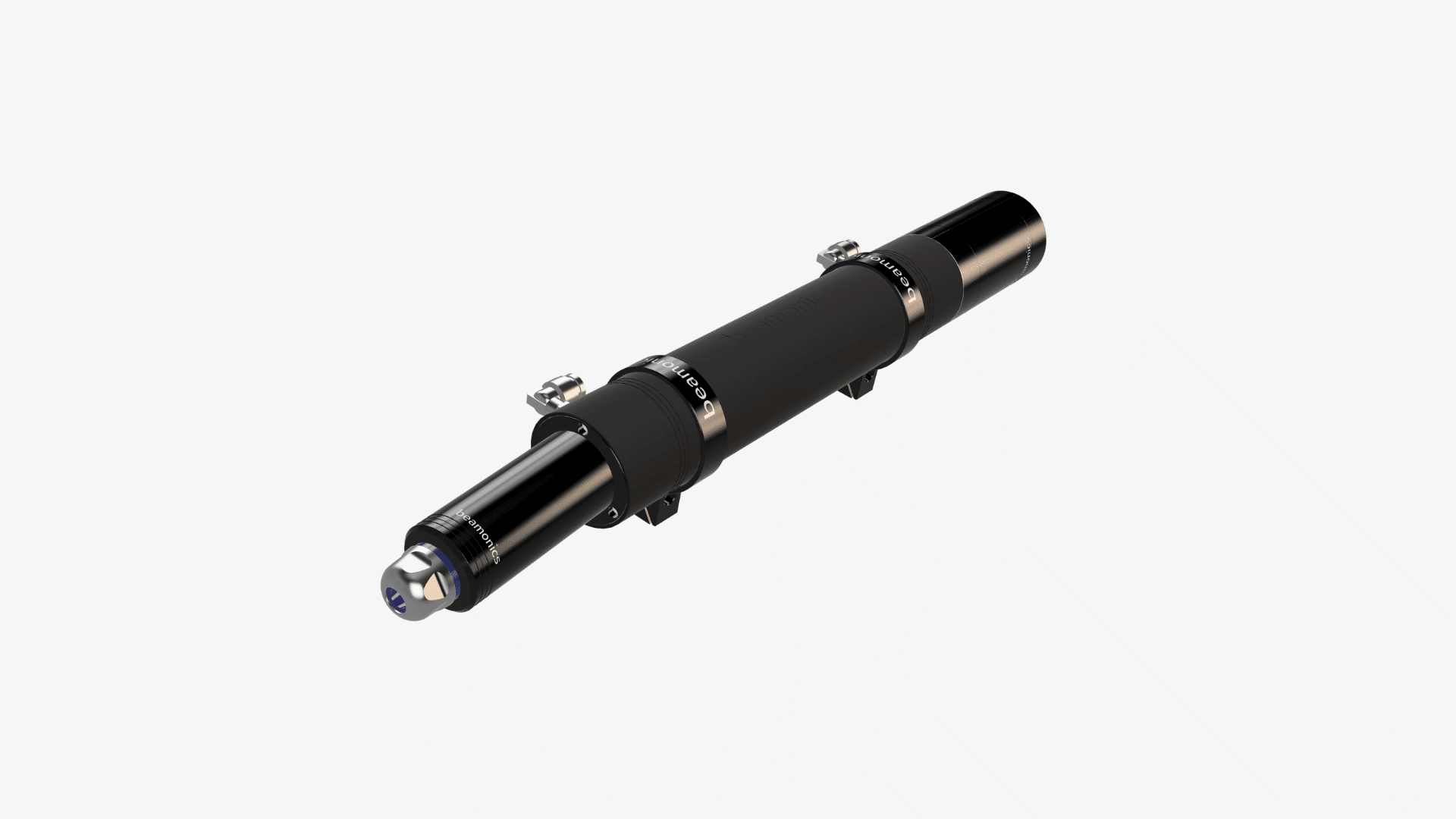
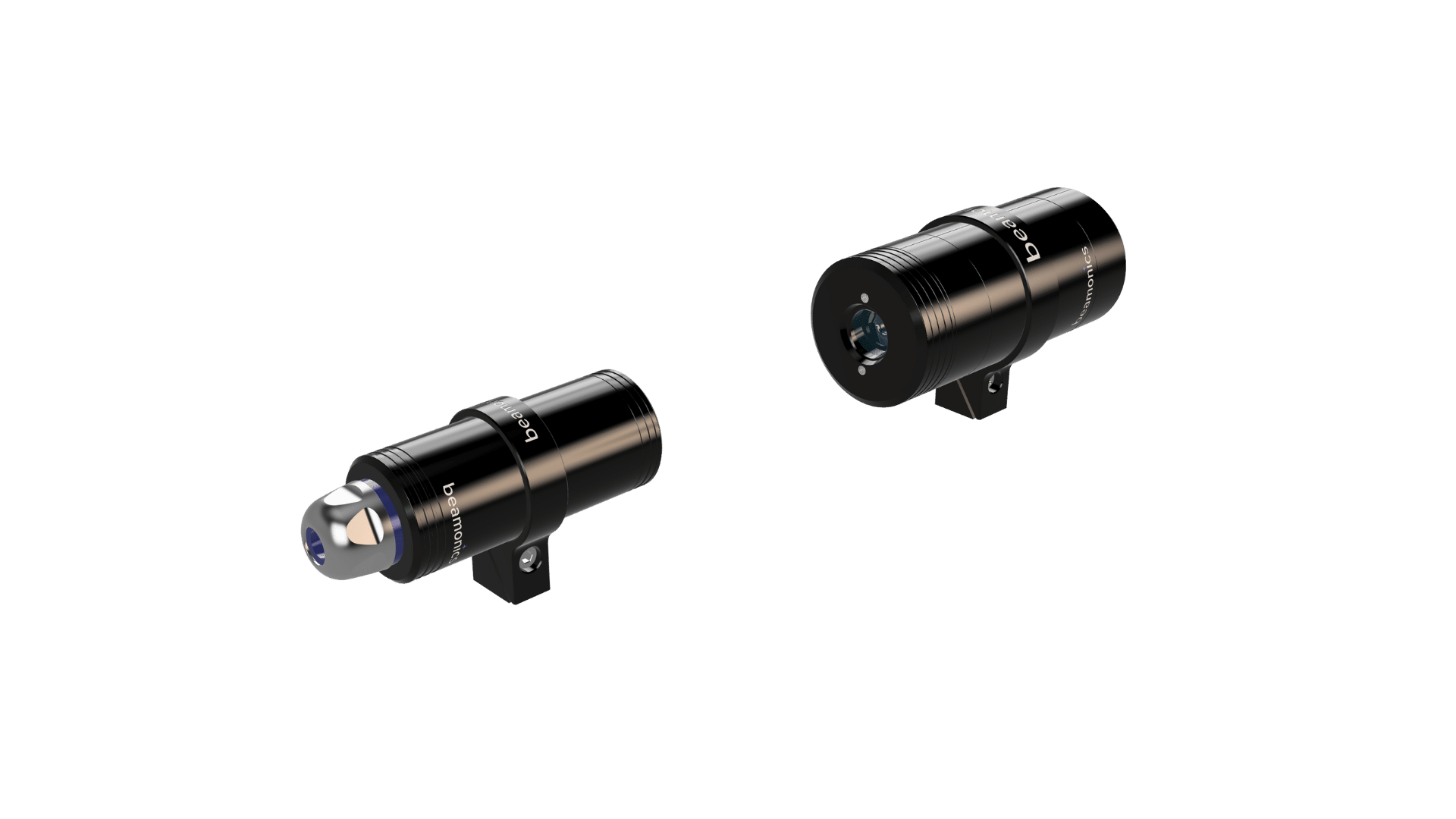
BeamCell serves this phase. Gas is drawn from the vicinity of the suspected leak through a short sample line into the flow chamber (0.185 m optical path) for measurement under controlled conditions. The extractive approach works in spaces too confined for open-path optics, and the sample conditioning inherent in the extractive setup (filtration, controlled flow rate) produces a clean measurement unaffected by ambient dust or steam plumes.
CH₄ precision is 1 ppm, H₂S precision is 1.5 ppm, NH₃ precision is 1 ppm, and HF precision is 0.05 ppm at the 0.185 m path length under standard test conditions (1 s averaging, 1 atm, 300 K). The fast spectroscopy allows rapid switching between sample points: a single BeamCell connected to a valve manifold can cycle through multiple suspected leak locations within seconds, confirming which components require repair without carrying multiple instruments.
The flow chamber’s acid-resistant construction tolerates corrosive species encountered in sour-service equipment, Claus unit piping, amine systems, and scrubber exhausts, where H₂S, HF, or acid mist would degrade an electrochemical sensor within hours.
For applications where cross-duct or short open-path measurement is feasible (vent ducts, enclosures, equipment bay exits), BeamStack provides in-situ measurement with higher precision: CH₄ at 0.2 ppm, H₂S at 0.3 ppm, NH₃ at 0.2 ppm at 1 m path length under standard test conditions. The path-averaged measurement captures the total gas burden across the duct cross-section, which is useful for quantifying the total emission rate from a vented enclosure when combined with a flow measurement.
Document and verify repair
After repair, a follow-up measurement at the same location confirms that the leak has been resolved. Beamonics TDLAS simplifies this step because the instrument’s reading is directly comparable between the pre-repair and post-repair surveys: there is no drift to account for and no recalibration required between measurements. The operator records the pre-repair concentration, the repair action, and the post-repair concentration as a matched pair.
For compliance documentation, the measurement data should be tied to component identification (tag number, location coordinates) and timestamped. Beamonics instruments output data via RS-485/422, USB, and analog interfaces, which can feed a data logger or mobile device running LDAR management software.
Specification summary for common LDAR target gases
| Gas | BeamSight (ppm·m, 8 m) | BeamCell (ppm, 0.185 m) | BeamStack (ppm, 1 m) |
|---|---|---|---|
| CH₄ | 15 | 1 | 0.2 |
| H₂S | 25 | 1.5 | 0.3 |
| NH₃ | 15 | 1 | 0.2 |
| HF | 0.05 | 0.05 | 0.01 |
| CO | 15 | 1 | 0.2 |
| CO₂ | 40 | 2.5 | 0.5 |
Standard test conditions: t = 0.5 s (BeamSight) or 1 s (BeamStack, BeamCell), P = 1 atm, T = 300 K. Precision is the largest of 1% relative and the specified value.
Practical Considerations
BeamSight reports ppm·m, not ppm. A reading of 150 ppm·m for CH₄ at 8 m range could represent a 19 ppm average over the full path, or a much higher concentration in a narrow plume occupying a fraction of the path. For leak localisation, the absolute ppm·m value matters less than the spatial pattern: where along the survey route the reading rises and falls. For emission quantification, converting ppm·m to a mass emission rate requires additional information (wind speed, plume geometry) or a dispersion model.
Beamonics instruments can handle transmission down to very low levels thanks to the proprietary platform, allowing surveys to continue uninterrupted in demanding outdoor conditions without regular cleaning and re-calibration.
Intermittent leaks, such as pressure-cycling valves, relief valves that lift briefly, and seals that leak only under certain operating conditions, may produce gas plumes lasting seconds. The real-time measurement of Beamonics TDLAS captures these events, but only if the instrument is pointed at the right location at the right time. For known intermittent sources, fixed monitoring with continuous data logging provides better coverage than periodic walking surveys.
FID and PID instruments remain useful as complementary screening tools, particularly for total-VOC assessment in applications where the regulatory framework requires Method 21-style measurements at individual components. Beamonics TDLAS does not replace Method 21 in regulatory contexts that specifically require it, but it provides gas-specific data that Method 21 does not, and it covers spatial areas that component-by-component screening cannot practically reach.
Application contexts
In upstream and midstream natural gas operations, methane is the primary target. Wellhead equipment, gathering-line connections, compressor stations, and storage terminals all contain potential fugitive sources. The combination of BeamSight surveys for rapid area screening and BeamCell confirmation at flagged components provides a systematic workflow that scales from small well pads to large processing facilities.
In refineries and petrochemical plants, H₂S and hydrocarbon leaks around sour-service piping, heat exchangers, and tank farm venting are priority targets. The spectral selectivity of Beamonics TDLAS distinguishes H₂S from the hydrocarbon background, which is something FID and PID instruments cannot do.
Around SCR installations and urea-handling systems, ammonia slip from catalyst-equipped stacks and fugitive NH₃ from piping and storage create both an emissions concern and a corrosion risk (ammonium bisulphate formation downstream of the SCR). BeamStack measuring NH₃ across the SCR outlet duct provides the process feedback signal, while BeamSight can survey the surrounding area for fugitive releases from urea piping and storage.
In landfill operations, CH₄ migration through cover material and along perimeter boundaries is monitored for both safety and greenhouse gas compliance. BeamSight’s ability to cover 30 m sight lines from a single position, combined with its sensitivity to atmospheric-background methane concentrations, makes it suitable for surface emission surveys and fence-line monitoring.
Closing Remark
The value of Beamonics TDLAS in LDAR is not only analytical sensitivity. It is the combination of gas-specific selectivity, fast spatial resolution at survey speed, and measurement stability that eliminates the calibration interruptions and drift-related false readings that slow conventional LDAR campaigns. Finding more genuine leaks per survey hour, with fewer false positives and clearer documentation of repair effectiveness, is a measurable operational improvement that compounds across every survey cycle.