In Brief
In-situ TDLAS analyzers measure gas directly across a duct, stack, or open space, delivering real-time response with no sample transport delay. Extractive TDLAS analyzers draw gas through a compact flow cell, which allows sample conditioning, multi-point sequencing, and protection of optics from harsh process environments. Both configurations use the same self-referencing measurement principle and neither requires routine field calibration. The choice between them is determined by the installation geometry, the condition of the process gas, and whether multi-point sampling is needed.
Background
Gas analysis in industrial processes serves combustion control, emissions compliance, safety monitoring, and product quality assurance. The value of any gas measurement depends on how accurately it represents conditions at the point of interest and how quickly it responds to changes. A reading that arrives too late to correct a process excursion, or one that drifts between calibration intervals, costs efficiency, risks non-compliance, and can delay safety response.
Traditional gas analyzers based on electrochemical cells or catalytic beads introduce drift over time, require periodic bump tests and span calibrations, and are susceptible to cross-interference and sensor poisoning. Beamonics TDLAS eliminates these issues by referencing the measurement to a molecular absorption line, a physical constant that does not change with sensor age, temperature, or chemical exposure. This stability applies equally to in-situ and extractive configurations, which means the choice between the two is driven by practical installation factors rather than by concerns about measurement integrity.
The question is straightforward: can the analyzer optics live at the measurement point, or does the gas need to be brought to the analyzer?
In-situ measurement: the analyzer at the process
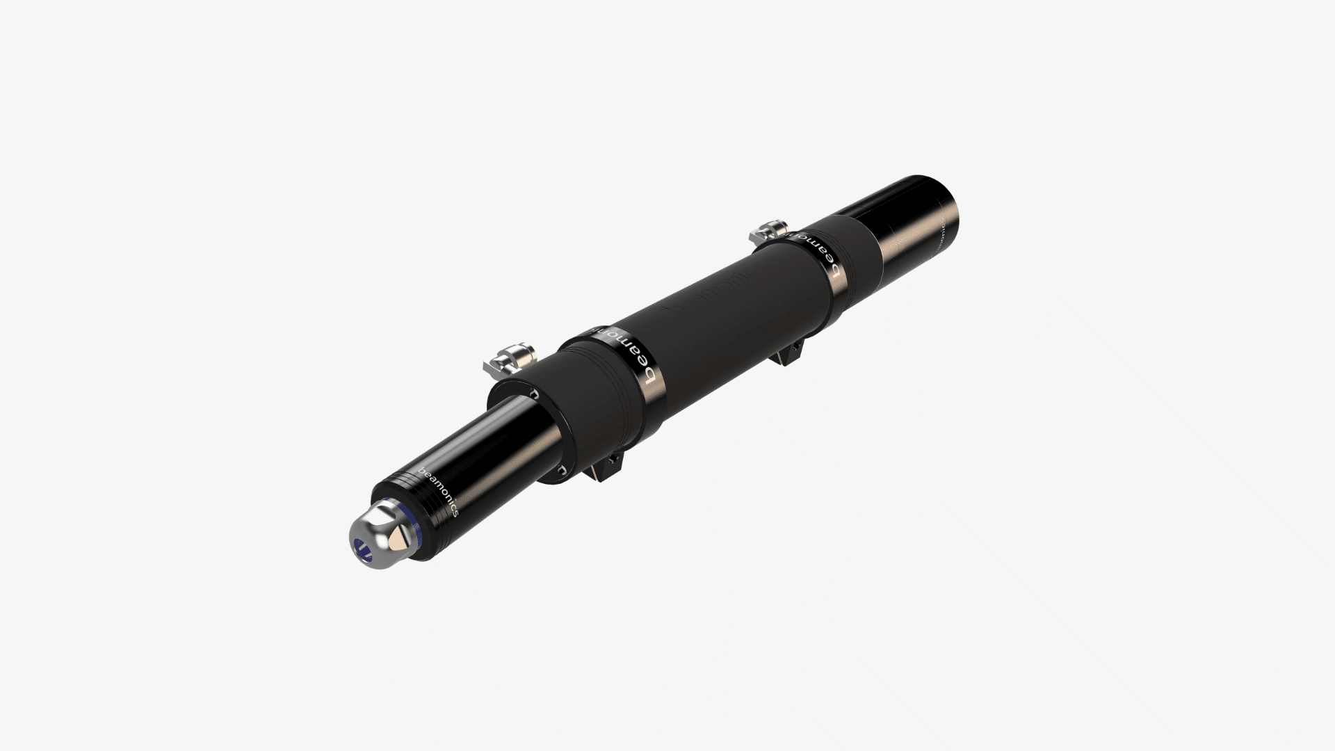
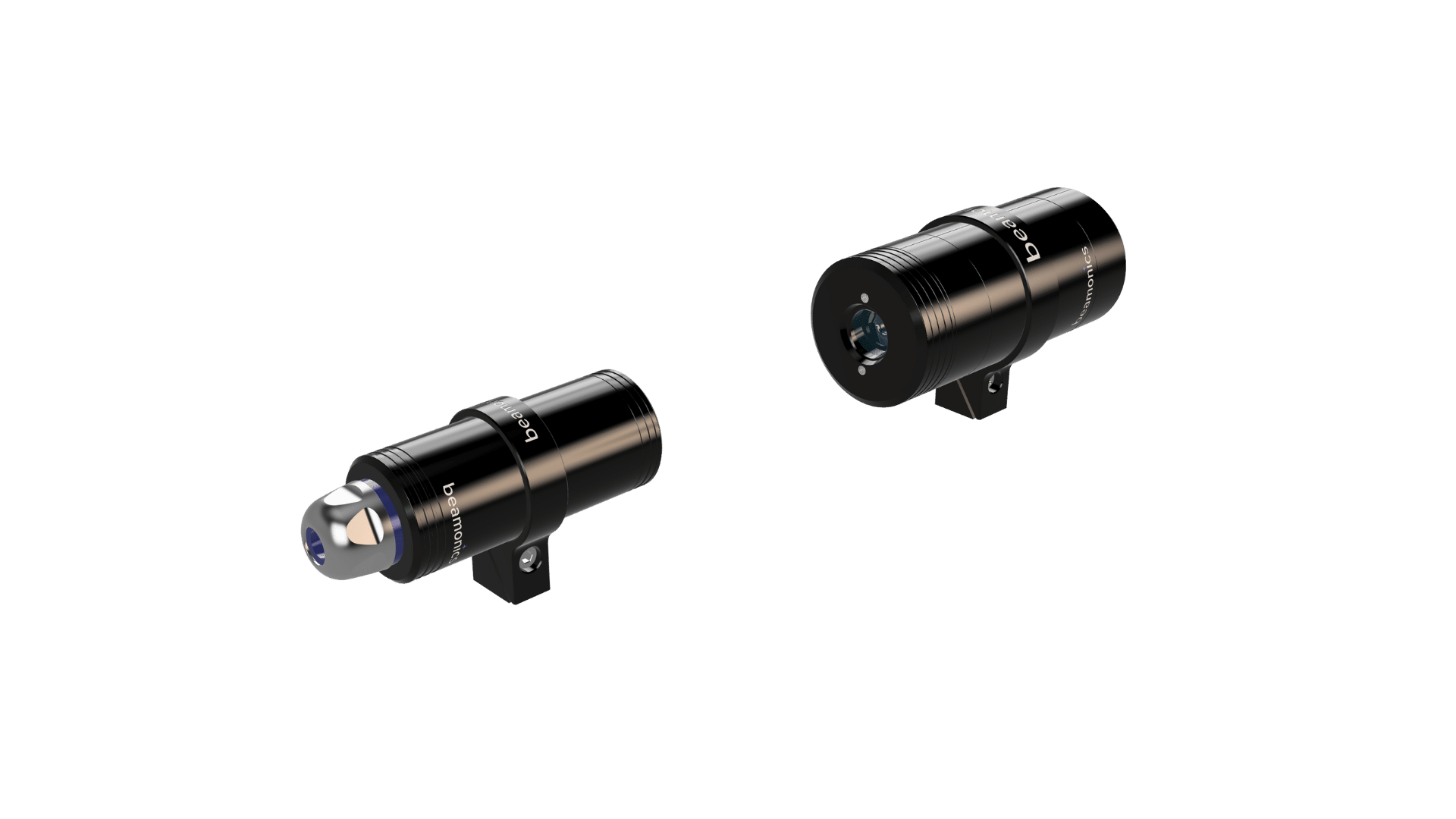
In an in-situ configuration, a laser transmitter and a receiver (or a combined transceiver) are mounted directly on the duct, stack, or open space where the gas exists. The laser beam passes through the process gas, and absorption is measured in real time with no sample extraction, no transport tubing, and no conditioning system. The gas is measured exactly where it is, in the conditions it actually occupies.
This approach has several direct consequences. Response is limited only by the spectroscopy rate, not by gas transit through a sample line. Beamonics BeamStack achieves analysis rates up to 10 kHz, meaning concentration changes are captured as they occur. There are no sample line losses, no condensation artifacts, and no risk of reactive gases (such as HF or NH₃) adsorbing onto tubing walls before reaching the analyzer. The measurement represents a path-averaged concentration across the full beam path, which in a stack or duct gives a spatially representative reading rather than a point sample from one location in the cross-section.
BeamStack is built for this role. The transmitter and receiver are IP67-rated, operate from −10 °C to 55 °C, and connect to plant control systems via RS-485, 4-20 mA, and relay outputs. Power consumption is 5 W. Startup time is approximately 5 seconds. Under standard test conditions (1 m path length, 1 s averaging, 1 atm, 300 K), analysis precision reaches 0.01 ppm for HF, 0.2 ppm for CO and CH₄, 0.5 ppm for CO₂, 0.3 ppm for H₂S, 0.2 ppm for NH₃ and H₂O, and 6 ppm for O₂.
In-situ measurement is the default choice when the installation geometry permits it: combustion control across a flue, continuous emissions monitoring across a stack, area surveillance across a room or corridor, and any application where real-time response and minimal maintenance are priorities.
Extractive measurement: the gas brought to the analyzer
In an extractive configuration, a sample probe or tap draws gas from the process and routes it through tubing to a flow cell where the TDLAS measurement takes place. The gas passes through the cell and is either returned to the process or vented. This introduces a transport delay, but in return it provides several capabilities that in-situ measurement cannot offer.
Sample conditioning. Process gas that carries heavy particulate, entrained liquids, condensable vapours, or extremely corrosive species may not be compatible with optics mounted directly in the flow. An extractive system can filter, heat, dry, or dilute the sample upstream of the analyzer, delivering clean gas to the measurement cell while protecting optical components. Beamonics BeamCell uses an acid-resistant flow chamber that withstands exposure to aggressive species including sulfuric acid, but even with this chemical resistance, some process streams benefit from upstream conditioning to remove particulate or condensate.
Multi-point sequencing. A single extractive analyzer connected to a valve manifold can sample from multiple process points in rapid succession. Because BeamCell reaches measurement-ready state within seconds and operates at analysis rates up to 10 kHz, switching between sample points and obtaining a stable reading at each one takes only a few seconds per point. This is considerably more cost-effective than installing a separate in-situ analyzer at each location, particularly when monitoring several taps along a reactor train, a header, or a tank battery.
Controlled measurement conditions. Inside the flow cell, temperature, pressure, and flow rate can be managed independently of process conditions. This simplifies the spectroscopic analysis and can improve precision for certain gases in extreme-temperature or high-pressure applications.
BeamCell connects via push-in G1/8 fittings for 6 mm or 8 mm gas tubing. It is IP67-rated, operates from −10 °C to 55 °C, and shares the same interface options as BeamStack: RS-485, USB, 4-20 mA, relay outputs, and expansion connectors. Under standard test conditions (0.185 m path length, 1 s averaging, 1 atm, 300 K), analysis precision reaches 0.05 ppm for HF, 1 ppm for CO and CH₄, 2.5 ppm for CO₂, 1.5 ppm for H₂S, 1 ppm for NH₃ and H₂O, and 30 ppm for O₂.
Remote stand-off: a third option
Some measurement scenarios do not fit cleanly into either the in-situ or extractive category. The gas may be in a location where neither mounting hardware on the duct nor running a sample line is practical: elevated piping, inaccessible tank tops, hazardous zones where personnel access is restricted, or open areas where no duct exists.
Beamonics BeamSight addresses these cases by operating as a stand-off analyzer that detects gas at distances up to 30 m (100 m with a reflector) without physical contact with the gas and without a remote receiver requiring alignment. It reports path-integrated concentration in ppm·m. The battery-powered portable configuration weighs 1.0 kg and provides approximately 5 hours of operation, supporting handheld surveys, drone-mounted inspections, and rover-based area scans.
BeamSight is not a replacement for in-situ or extractive analyzers in process control applications, since it measures path-integrated rather than point concentration. It fills a different role: rapid area screening, leak detection, and access to measurement points that would otherwise require scaffolding, shutdown, or hazardous-area entry.
Choosing between in-situ and extractive
The decision rests on a few practical questions about the specific installation.
Can optics be mounted at the measurement point? If the duct or space allows line-of-sight mounting of a transmitter and receiver, and the process gas does not carry heavy particulate, entrained liquid, or conditions that would rapidly foul optical windows, in-situ is the simpler installation. It eliminates sample lines, pumps, filters, and the maintenance that comes with them.
Does the gas stream require conditioning? If the process gas is laden with dust, carries condensable tars or water, or contains species that deposit on surfaces, extractive sampling with upstream filtration and heating protects the measurement optics and ensures a clean, representative sample reaches the cell.
Is multi-point monitoring needed? If the application requires concentration data from several process taps, a single extractive BeamCell with a valve manifold is more practical and economical than multiple in-situ installations.
How critical is response time? In-situ response is essentially instantaneous at the spectroscopy rate. Extractive response includes the transport delay through the sample line, typically a few seconds depending on line length and flow rate. For combustion control or fast safety interlocks, that difference may matter. For process monitoring or compliance averaging, it usually does not.
What are the access and maintenance conditions? In-situ analyzers require periodic optical inspection. Extractive analyzers require filter changes, line inspections, and flow verification, but the analyzer itself can be mounted in an accessible location regardless of where the sample point is. Neither configuration requires routine span calibration.
Specification comparison
| Parameter | BeamStack (in-situ) | BeamCell (extractive) |
|---|---|---|
| Measurement type | Cross-stack / open-path | Flow-through cell |
| Path length (test conditions) | 1 m | 0.185 m |
| HF precision | 0.01 ppm | 0.05 ppm |
| CO precision | 0.2 ppm | 1 ppm |
| CO₂ precision | 0.5 ppm | 2.5 ppm |
| CH₄ precision | 0.2 ppm | 1 ppm |
| H₂S precision | 0.3 ppm | 1.5 ppm |
| NH₃ precision | 0.2 ppm | 1 ppm |
| H₂O precision | 0.2 ppm | 1 ppm |
| O₂ precision | 6 ppm | 30 ppm |
| Analysis rate | 1 Hz to 10 kHz | 1 Hz to 10 kHz |
| Operating temperature | −10 °C to 55 °C | −10 °C to 55 °C |
| IP classification | IP67 | IP67 |
| Supply voltage | 15 to 32 VDC | 15 to 32 VDC |
| Power consumption | 5 W | 5 W |
| Startup time | ~5 s | ~5 s |
| Multi-point capability | No | Yes, via valve manifold |
All precision values under standard test conditions: P = 1 atm, T = 300 K, 1 s averaging. Largest of 1% relative and specified precision applies.
The difference in precision between BeamStack and BeamCell reflects the difference in optical path length (1 m vs. 0.185 m), not a difference in measurement quality. Both instruments use the same Beamonics TDLAS platform.
Practical Considerations
In-situ analyzers report a path-averaged concentration across the full beam width. This is representative in well-mixed flows but may understate localised concentration peaks in stratified or unmixed conditions. For stratified stacks, consider multiple beam paths at different heights or complement with extractive point sampling.
Extractive sample lines introduce a transport delay and potential for sample loss. Reactive gases such as HF and NH₃ can adsorb onto metal or polymer tubing surfaces, particularly in cold or humid conditions. Keeping sample lines short, heated where necessary, and constructed from appropriate materials (PTFE, treated stainless steel) minimises these effects.
Beamonics instruments can handle transmission down to very low levels thanks to the proprietary platform, allowing processes to run uninterrupted without regular cleaning and re-calibration. Both BeamStack and BeamCell monitor optical signal levels internally and report diagnostic warnings when attenuation indicates attention is needed.
Both configurations share the same calibration-free, self-referencing Beamonics TDLAS core. Neither requires bump tests, reference gas bottles, or scheduled span adjustments. Verification, if desired, can be performed by exposing the instrument to a known reference gas, but this is a functional check, not a recalibration.
Closing Remark
In-situ and extractive TDLAS are not competing technologies. They are two installation strategies for the same measurement principle, each optimised for different site conditions. Where optics can live at the process and the gas stream is optically manageable, in-situ provides the fastest response with the least infrastructure. Where the gas needs conditioning, where multiple points must be monitored from one analyzer, or where the measurement location is physically hostile to optical hardware, extractive provides the same selectivity and stability with more flexibility in system design. Identifying which set of constraints applies to the specific installation resolves the choice.